
Replacement Part List


“D SERIES” HG
Master Appliance Corp.
2420 18
th
St.
Racine, WI 53403-2381 USA
Tel: 262-633-7791
Email: sales@masterappliance.com
www.masterappliance.com
58278E REV A
pg. 5 of 6
2. Attach the piggyback terminal of the jumper to the switch, and
the other end of the jumper to the switch (Figure 8).
3. Place the electrical barrier Ⓥ between the switch and the
housing.
4. Align the three holes of the bezel with the three tabs in the
handle and gently press the switch / bezel assembly into position
as shown (Figure 4).
5. Position the shrink tube over the piggyback terminal and over
the white wire terminals from the motor and from the cordset.
Use cable ties to hold in place (Figure 10).
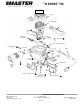
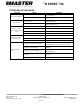
To install the HANDLES and COVER: (Figure 10)
1. Hook the left handle onto the handle portion of the metal
housing.
2. Install switch bezel assembly per above.
3. Ensure the electrical barrier Ⓥ is positioned between the
terminals of the switch and the housing.
4. Align the three holes of the switch bezel with the three tabs in
the handle and gently press the switch / bezel assembly into
position as shown (Figure 5).
5. Route wires in channels (Figure 10) and tighten cable ties to
hold wiring in place.
6. Ensure all wiring clears the screw holes of the handles and
gently assemble the right handle onto the housing (Figure 10).
Retain with #6-19 x .63 screws Ⓙ (4) (Figure 1). Tighten to 12 –
15 in-lbs torque.
7. Assemble cover onto housing and retain with housing screws,
#6-32 x .50 screws, Ⓗ (2) (Figure 1). Tighten to 16 - 20 in-lbs
torque.
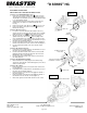
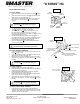
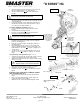
To install element nozzle and shield: (Figures 11 & 12)
1. Gently insert new element into housing, with contacts of element
contacts inserted fully into the contacts in the housing.
2. Wrap the mica insulator around coils of heater element, ensuring
all coils are covered.
3. Gently slide nozzle straight on, aligning ceramic element wings
with front nozzle indents and two (2) nozzle screw holes.
4. Slide shield over nozzle, aligning mounting holes.
5. Install two (2) nozzle screws Ⓦ loosely until started, and then
tighten.
AFTER HEAT GUN IS COMPLETELY ASSEMBLED, CONDUCT
FINAL ADJUSTMENT AND TEST:
1. Plug your Master heat gun® into a properly rated electrical
outlet.
2. Run in cool mode, gently tap bottom of unit to align motor
bearings unit until motor noise stabiles.
3. Switch unit to “Hot”. Hot air should be blowing from nozzle.
Element
Mica
Nozzle
Indents align with element
wings.
Shield
Figure 12
Ⓦ
Ⓦ
WARNING: Failure to insulate switch & wire terminals from
metal enclosure could result in electrical short
ENSURE WIRES STAY
CLEAR OF SCREW
HOLES AND HANDEL
PINCH POINTS TO
AVOID PINCHING
WIRES BETWEEN
HANDLES
ENSURE BARRIER
IS BETWEEN
TERMINAL AND
METAL HANDEL
ELEMENT
CONNECTOR
Figure 10
Ⓥ
CORD CLAMP BETWEEN
CORDSET AND METAL HOUSING,
ONLY USED ON EUROPEAN, U.K.,
AND 220-240V CORDSETS
WARNING:
Failure to properly cover coils
with mica insulator could result in electrical short
WARNING: Failure to insulate switch & wire terminals from
metal enclosure could result in electrical short
New element
Element wings
Insert into contacts
Contacts in housing
New mica
Roll mica over coils of
element
Figure 11