
User`s manual


registers is acceptable), and then wait 16 additional cycles for all of our data
to be produced on the SDO line. We rotate between a state for reading the x
registers and a state for reading the y registers. We feed the produced x and
y readings into instantiations of the moving avg filter. The output of the acc
module is the output of these filters.
One challenge we faced was getting the accelerometer clock period correct.
Even though the spec states that the maximum clock frequency is 5 MHz, if we
use a 5 MHz clock and then use a single clock cycle to implement the t
CS,DIS
waiting period shown in Figures 5 and 6 of the timing diagram, we will not meet
the minimum t
CS,DIS
spec of 250ns. So we had to pick a clock frequency lower
than
1s
250ns
= 4 MHz to use a one-cycle wait to meet the t
CS,DIS
spec. This bug
took quite a while to find.
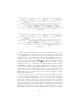
The picture below shows the accelerometer module working in isolation, with
averaged accelerometer readings displayed on the hex display:
Figure 3: Accelerometer readings on hex display
13