
Operator's Manual
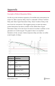
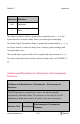
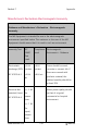
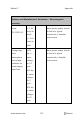
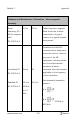
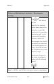
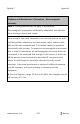
Table Of Contents
- About this Manual
- Product Description
- Indications for Use
- Contraindications
- Warnings and Cautions
- Chapter 1: Technology Overview
- Signal Extraction Technology (SET)
- rainbow Pulse CO-Oximetry Technology®
- Pulse CO-Oximetry vs. Drawn Whole Blood Measurements
- General Description for Total Hemoglobin (SpHb)
- General Description for Total Arterial Oxygen Content (CaO2)
- General Description for Carboxyhemoglobin (SpCO)
- General Description for Methemoglobin (SpMet)
- General Description for Oxygen Reserve Index (ORI)
- SpCO, SpMet, and SpHb Measurements During Patient Motion
- rainbow Acoustic Monitoring (RAM) Technology
- Chapter 2: Radical-7 Descriptions
- Chapter 3: Setup
- Chapter 4: Operation
- Using the Touchscreen and Buttons
- Using Screen Lock
- Using the Home Button
- Standby and Power Off
- Navigating the Radical-7
- About the Display View
- Sensitivity Modes Overview
- Changing Sensitivity Modes
- Accessing the Main Menu
- Navigating the Main Menu
- Parameter Settings
- Chapter 5: Profiles
- Chapter 6: Alarms and Messages
- About Alarms
- Silencing the Alarms
- Adaptive Threshold alarm (ATA) Feature
- 3D Alarms
- Messages
- Replace Sensor Message
- Replace Cable Message
- Replace Adhesive Sensor Message
- Incompatible Sensor Message
- Incompatible Adhesive Sensor Message
- No Adhesive Sensor Connected Message
- Interference Detected Message
- SpO2 Only Mode Message
- RAM Check Sensor Message
- RAM Sensor Initializing Message
- Low Battery Message
- Low Perfusion Index Message
- Low Signal IQ Message
- Low SpCO SIQ Message
- Low SpMet SIQ Message
- Low SpHb SIQ Message
- Speaker Failure Message
- Invalid Parameter Alarm Message
- No Cable Connected Message
- No Sensor Connected Message
- Pulse Search Message
- Sensor Initializing Message
- Sensor Off Patient Message
- Incompatible Cable Message
- Near Expiration Message
- Chapter 7: Troubleshooting
- Chapter 8: Specifications
- Chapter 9: Service and Maintenance
- Appendix
- Index

Radical-7 Appendix
www.masimo.com 212 Masimo
Reference
Definition
SpO
2
Saturation
t Time
The Alarm Condition Delay is graphically represented as t
2
– t
1
in the
figure above to show the delay due to processing and averaging.
The Alarm Signal Generation Delay is graphically represented as t
3
– t
2
in
the figure above to show the delay due to alarm system strategy and
communication time.
The overall alarm system delay time is graphically represented as t
3
– t
1
.
For more information about alarm response delay, refer to ISO 80601-2-
61.
Guidance and Manufacturer's Declaration- Electromagnetic
Emissions
Guidance and Manufacturer's Declarations - Electromagnetic
Emissions
The ME Equipment is intended for use in the electromagnetic
environment specified below. The customer or the user of the ME
Equipment should assure that it is used in such an environment.
Emission Test Compliance
Electromagnetic Environment -
Guidance