
Operator's Manual
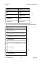
Table Of Contents
- About this Manual
- Product Description
- Indications for Use
- Contraindications
- Warnings and Cautions
- Chapter 1: Technology Overview
- Signal Extraction Technology (SET)
- rainbow Pulse CO-Oximetry Technology®
- Pulse CO-Oximetry vs. Drawn Whole Blood Measurements
- General Description for Total Hemoglobin (SpHb)
- General Description for Total Arterial Oxygen Content (CaO2)
- General Description for Carboxyhemoglobin (SpCO)
- General Description for Methemoglobin (SpMet)
- General Description for Oxygen Reserve Index (ORI)
- SpCO, SpMet, and SpHb Measurements During Patient Motion
- rainbow Acoustic Monitoring (RAM) Technology
- Chapter 2: Radical-7 Descriptions
- Chapter 3: Setup
- Chapter 4: Operation
- Using the Touchscreen and Buttons
- Using Screen Lock
- Using the Home Button
- Standby and Power Off
- Navigating the Radical-7
- About the Display View
- Sensitivity Modes Overview
- Changing Sensitivity Modes
- Accessing the Main Menu
- Navigating the Main Menu
- Parameter Settings
- Chapter 5: Profiles
- Chapter 6: Alarms and Messages
- About Alarms
- Silencing the Alarms
- Adaptive Threshold alarm (ATA) Feature
- 3D Alarms
- Messages
- Replace Sensor Message
- Replace Cable Message
- Replace Adhesive Sensor Message
- Incompatible Sensor Message
- Incompatible Adhesive Sensor Message
- No Adhesive Sensor Connected Message
- Interference Detected Message
- SpO2 Only Mode Message
- RAM Check Sensor Message
- RAM Sensor Initializing Message
- Low Battery Message
- Low Perfusion Index Message
- Low Signal IQ Message
- Low SpCO SIQ Message
- Low SpMet SIQ Message
- Low SpHb SIQ Message
- Speaker Failure Message
- Invalid Parameter Alarm Message
- No Cable Connected Message
- No Sensor Connected Message
- Pulse Search Message
- Sensor Initializing Message
- Sensor Off Patient Message
- Incompatible Cable Message
- Near Expiration Message
- Chapter 7: Troubleshooting
- Chapter 8: Specifications
- Chapter 9: Service and Maintenance
- Appendix
- Index

Radical-7 Chapter 8: Specifications
www.masimo.com 190 Masimo
Analog Output and Nurse Call Specifications
Analog Out and Nurse Call are accessible on the same female high-
density DB-15 connector. Analog Output and Nurse Call interface are only
available when the Handheld is attached to the Docking Station. Only use
an Analog and Nurse Call cable that has a ferrite bead installed. Analog
Output and Nurse Call interface is not available in all versions of the
Docking Station. See
Nurse Call Test
on page 201 and
Handheld Front
Panel
on page 49.
The following table shows the pin out of the Analog Output and Nurse
Call.
Pin
Signal Name
1 +5V (60mA max.)
2 Ground
3 Ground
4 Ground
5 Ground
6 Nurse Call (Normally Open)
7 Nurse Call (Normally Closed)
8 Ground
9 Analog 1