
Operator's Manual
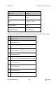
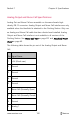
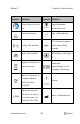
Table Of Contents
- About this Manual
- Product Description
- Indications for Use
- Contraindications
- Warnings and Cautions
- Chapter 1: Technology Overview
- Signal Extraction Technology (SET)
- rainbow Pulse CO-Oximetry Technology®
- Pulse CO-Oximetry vs. Drawn Whole Blood Measurements
- General Description for Total Hemoglobin (SpHb)
- General Description for Total Arterial Oxygen Content (CaO2)
- General Description for Carboxyhemoglobin (SpCO)
- General Description for Methemoglobin (SpMet)
- General Description for Oxygen Reserve Index (ORI)
- SpCO, SpMet, and SpHb Measurements During Patient Motion
- rainbow Acoustic Monitoring (RAM) Technology
- Chapter 2: Radical-7 Descriptions
- Chapter 3: Setup
- Chapter 4: Operation
- Using the Touchscreen and Buttons
- Using Screen Lock
- Using the Home Button
- Standby and Power Off
- Navigating the Radical-7
- About the Display View
- Sensitivity Modes Overview
- Changing Sensitivity Modes
- Accessing the Main Menu
- Navigating the Main Menu
- Parameter Settings
- Chapter 5: Profiles
- Chapter 6: Alarms and Messages
- About Alarms
- Silencing the Alarms
- Adaptive Threshold alarm (ATA) Feature
- 3D Alarms
- Messages
- Replace Sensor Message
- Replace Cable Message
- Replace Adhesive Sensor Message
- Incompatible Sensor Message
- Incompatible Adhesive Sensor Message
- No Adhesive Sensor Connected Message
- Interference Detected Message
- SpO2 Only Mode Message
- RAM Check Sensor Message
- RAM Sensor Initializing Message
- Low Battery Message
- Low Perfusion Index Message
- Low Signal IQ Message
- Low SpCO SIQ Message
- Low SpMet SIQ Message
- Low SpHb SIQ Message
- Speaker Failure Message
- Invalid Parameter Alarm Message
- No Cable Connected Message
- No Sensor Connected Message
- Pulse Search Message
- Sensor Initializing Message
- Sensor Off Patient Message
- Incompatible Cable Message
- Near Expiration Message
- Chapter 7: Troubleshooting
- Chapter 8: Specifications
- Chapter 9: Service and Maintenance
- Appendix
- Index

Radical-7 Chapter 8: Specifications
www.masimo.com 189 Masimo
Parameter Setting
Parity None
Bits 1 start, 1 stop
Handshaking None
Connector type Female DB-9
The pin-outs for the RS-232 connector are shown in the following table:
Pin
Signal name
1 No Connection
2 Receive data – RS-232 ±9 V (±5 Vmin)
3 Transmit data – RS-232 ±9 V (±5 Vmin)
4 No Connection
5 Signal Ground Reference for COM signals
6 No Connection
7 No Connection
8 No Connection
9 No Connection