
Owners Guide

18
The following are detailed procedures for replacement of specic funconal components of the Marvel 6CRF
Refrigerator, NSN 4110-01-629-6841. Before beginning work, you should have on hand, at a minimum, the
tools recommended in the list at par. 1-9, and the specied replacement part for the refrigerator. Each sepa-
rate procedure below tells you what replacement parts to have on hand, how to remove the defecve parts,
then how to install the replacements.
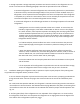
3-7 Fan Assembly Replacement (Service Assembly 42246338)
a. Posion the refrigerator for easy access to front and back.
b. Using a phillips screwdriver remove the (2) screws holding the grill to the front of the cabinet just
below the door. Set the screws and grille aside for later reassembly. Remove the (4) phillips head screws
and washers (2 on each side) holding the cabinet wrapper to the base plate. Set the screws and wash-
ers aside for later reassembly.
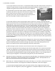
c. With the 5/16” nut driver remove the (9) screws holding the back shield to the cabinet and set aside
for later reassembly.
d. Using the 5/16” nut driver, remove the mounng screws from the cabinet back, and remove the
back. Put the back and the 14 screws aside for later re-assembly. Recessed into the foam
insulaon, both the large copper sucon return line from the evaporator and the thin capillary tube
carrying cold liquid from the lter/dryer to the evaporator run up to the upper le corner. Under these
lines is the thin aluminum capillary tube/sensor line from the thermostat.
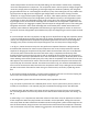
e. With the 5/16” nut driver remove the (2) screws holding the cabinet wrapper to the base plate.
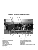
See Figure 3-1 item 16.
CAUTION
THE 32-LB MECHANICAL ASSEMBLY IS STILL FULLY ATTACHED TO THE
REFRIGERATION SYSTEM
YOU CAN MOVE THE ASSEMBLY ONLY A FEW INCHES OUT OF THE COMPARTMENT
WITHOUT DANGER OF DAMAGING THE COPPER REFRIGERANT LINES
BE SURE THAT YOUR WORK SURFACE IS WIDE ENOUGH TO SUPPORT THE
MECHANICAL ASSEMBLY WHEN YOU HAVE IT PULLED 4” TO 6” BACK
FROM ITS OPERATIONAL POSITION, AND ROTATED A FEW DEGREES
HORIZONTALLY...
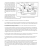
f. Refer to g. 3-1 Refrigerator Mechanical Assembly. The mechanical assembly is comprised of all the
components mounted on the steel base plate at the rear of the refrigerator, g. 3-1.
g. Locate the wire leads from the fan motor and follow them back to the molex connector from the
wire harness. Unplug the fan connector from the wire harness.
h. Use a 3/8” open or box end wrench to remove the (2) nuts fastening the boom of the fan
motor bracket to the base plate. Set the nuts aside for later re-assembly. Carefully pull the fan assem-
bly up and away from the fan guard, toward the compressor, and li it clear. Discard the old fan assem-
bly.
i. Assembly is the reverse of the above procedure.