
Owners Guide


12
2.4 Installaon, connued.
c. At the upper le front corner there is a snap fastened safety strap which holds the door closed during
shipment. To open the door, unsnap the safety strap and pull outward on the door. The door has a
magnec door gasket which provides the seal for the refrigerator.
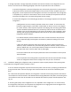
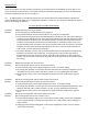
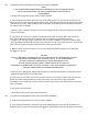
d. Install handle to top of door. With a phillips screwdriver remove
the buon snap from the top of the door. Place the handle on the
door as shown and secure with (2) hex cap screws provided,
using the 5/32” hex key. Secure the buon snap to the top of the
door with the phillips screwdriver. Refer to Figure 2-1.
Figure 2-1
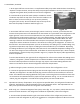
e. At the lower le front corner, behind the grill, which is held on by 2 screws, you will nd the ther-
mostat. The n plated sensor line aached to the thermostat runs up the back of the refrigerator to the
upper right rear corner. The sensor lies between the rear panel and the insulaon. The dial of the
thermostat has an adjustment range of 1 to 7 (7 is the coldest seng). The seng point of the ther-
mostat dial is determined by what number is visible at the twelve o’clock posion. When the “OFF”
leering is visible on the thermostat dial at the twelve o’clock posion, power to the refrigerator’s
compressor and the condenser fan motor is shut-o and no cooling of the refrigerator or freezer sec-
on will occur. The thermostat posion is pre-set at the factory to a seng of 4, or middle seng. Vary
ing ambient temperature may require re-seng the thermostat dial for your installaon. Depending
on loading condions of your refrigerator, allow 24 hours for new stabilized temperature sengs to oc-
cur with each change to the thermostat dial. To facilitate the inial compartment pull - down to operat-
ing temperature, remove the drip tray (item #3 in Figure 1-1). Replace the drip tray aer approximately
3 hours of operaon.
f. See the label located on the right side of the refrigerator for reference thermostat dial sengs versus
ambient / refrigerator / freezer temperatures in unloaded condions. Actual amounts of commodies
and their inial temperatures and means of usage may require a thermostat seng dierent than
shown on the label to achieve desired refrigerator and freezer temperatures.
g. Before making the power connecon, be sure that the interior of the refrigerator is clean.
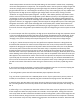
h. Connect the appropriate electrical plug into the electrical supply outlet. For an outlet that provides
230 VAC, the refrigerator’s 115 VAC electrical plug must be inserted into the transformer’s electrical
outlet. The 230 VAC electrical plug aached to the power cord coming from the transformer must then
be inserted into the 230 VAC outlet for proper and safe operaon. See g. 1-2. For 115 VAC electrical
outlets, plug the refrigerator’s 115 VAC electrical plug directly into the 115 VAC outlet.
2.5 Operaon and Theory of Operaon. Once prepared as specied above, the refrigerator funcons auto-
macally. The following is a brief explanaon of how the refrigerator works. This explanaon will en-
able you to operate and maintain the refrigerator most eciently.
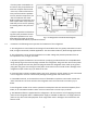
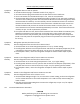
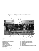
2.6 Refer to g. 2-2. a funconal diagram of the system, and to gs. 4-1, 4-2, and 4-3, which show the com-
ponents and their locaon in the refrigerator. To follow the explanaon, refer to these gures.
a. The thermostat (located behind the grill at the lower le front of the refrigerator) monitors tem-
peratures inside the refrigerator by way of the evaporator or cold plate temperature. When the sensor