OPERATION AND MAINTENANCE OF MECHANICAL FIELD WARD REFRIGERATOR NSN4110-01-629-6841 MARVEL MODEL #4570105-MODIFIED-230/115 VOLT, 60/50 Hz. CONTRACT # Marvel Refrigeration 1260 E. VanDeinse St. Greenville MI 48838 800.223.
CONTENTS CHAPTER/PARAGRAPH PAGE 1. Introduction ............................................................................................................................................... 4 1-1 Introduction ............................................................................................................................... 4 1-2 Warning .....................................................................................................................................
LIST OF ILLUSTRATIONS FIGURE NUMBER DESCRIPTION 1-1 Refrigerator, Front View ................................................................................................................... 1-2 Refrigerator, Rear View .................................................................................................................... 2-1 Door Handle Installation .................................................................................................................
CHAPTER 1 1-1 Introduction INTRODUCTION 1-2 This operation and maintenance manual provides you with the necessary information for using and maintaining the Mechanical and Biological Refrigerator, NSN 4110-01-629-6841. The manual includes information for operation, preventive maintenance, and corrective maintenance.
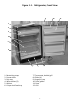
Figure 1-1. Refrigerator, Front View 9 1 2 3 4 5 6 7 1. Restraining strap 2. Freezer door 3. Drip tray 4. Wire shelves (2) 5. Cabinet 6. Crisper shelf and tray 12 8 7. Thermostat, behind grill 8. Glides (4) 9. Hinge pin, top 10. Door gasket 11. Door 12.
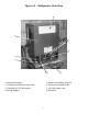
Figure 1-2. Refrigerator, Rear View 4 1 5 6 2 3 8 1. Cabinet back cover 2. Transformer/230 Volt Power Cord 3. Transformer/ 115 Volt outlet 4. Wiring diagram 7 5. Power cord holding strap (2) 6. Stainless steel back shield 7. 115 Volt power cord 8.
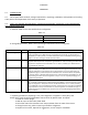
1-7 The outer shell of the refrigerator and the door cover are 1/32nd inch carbon steel with olive drab finish. The inner shell and door liner are plastic. The door has a magnetic latch. There is a door security snap fastener located at the upper left corner for use during transport. 1-8 Specifications. Table 1-1 lists the complete specifications and parameters for the refrigerator, NSN 4110-01-629-6841. Table 1-1 Parameter Specification Acceptable input voltages 115/230 VAC.
1-10 Safety. ALWAYS observe the warning notice shown after paragraph 1-2 above. Always disconnect power before servicing. Failure to do so could result in property damage, physical injury, or death. For connection to a 230 VAC source, be sure to use the step down transformer, as detailed in par. 2.4h, below. 1-11 When the refrigerator is in operation, the condenser (radiator), the compressor, and the refrigerant lines can get hot enough to burn the skin.
CHAPTER 2 OPERATION 2-1 INTRODUCTION 2-2 This chapter details shelf life, storage requirements, unpacking, installation, and operation of the refrigerator, with a brief explanation of the theory of operation. 2-3 SHELF LIFE STORAGE REQUIREMENTS, UNPACKING PROCEDURES, PACKAGING, AND PRESERVATION AND STORAGE INSPECTION. a. Shelf life. Table 2-1 lists the shelf life for the refrigerator.
d. Packaging and Preservation Refrigerators that have been uncartoned and used in service require that the following procedures be done to them before they are made inactive and placed in storage. 1. Turn the thermostat knob to the “OFF” position to deactivate the refrigerator and before removing the electrical plug(s) from the electrical supply outlet(s). The “OFF” position on the thermostat knob is achieved when the “OFF” marking on the knob is at the twelve o’clock position. 2.
e. Storage Inspection. Storage inspection procedures are based on whether the refrigerators are cartoned or uncartoned. The following paragraphs describe the procedures for both conditions. 1. Cartoned refrigerators. Cartoned refrigerators are to be visually inspected on a periodic basis to determine if they have been damaged and/or if they are wet. If either condition exists, the refrigerator is to be removed from the damaged or wet carton and inspected.
2.4 Installation, continued. c. At the upper left front corner there is a snap fastened safety strap which holds the door closed during shipment. To open the door, unsnap the safety strap and pull outward on the door. The door has a magnetic door gasket which provides the seal for the refrigerator. d. Install handle to top of door. With a phillips screwdriver remove the button snap from the top of the door.
shows a temperature warmer than the adjusted setting, the thermostat’s contacts close, completing the circuit that operates the compressor. The compressor takes in the low pressure refrigerant gas and converts it to high pressure refrigerant gas. Passing through the condenser (radiator), the refrigerant gas gives off heat to the air surrounding the condenser, by way of the cooling fins, like any radiator.
from the power cord attaches to the starter relay and provides the means to complete the electrical circuit. So, a failure of the starter relay can also look like a problem not only with the compressor, but also the condenser fan motor. Before replacing a compressor, test with a spare starter relay and overload that you can use for replacing the existing starter relay and overload.
CHAPTER 3 3-1 INTRODUCTION MAINTENANCE 3-2 This chapter covers preventive and corrective maintenance, including a recommended schedule of maintenance and a brief trouble shooting guide. 3-3 SAFETY In working on this refrigerator, be sure to ALWAYS observe the elements of safety cited in the general introduction, par. 1-2, and at par. 1-9. Before performing any of the following, ALWAYS be sure that the refrigerator is unplugged from its power. 3-4 Preventive Maintenance.
SEMIANNUALLY Check the condenser coil, fan assembly, compressor, and transformer for accumulation of dirt or dust. If necessary clean with vacuum cleaner. For removal of stainless steel back shield to gain access to the mechanical assembly compartment see par. 3-7c and fig. 1-2. 3-5 Troubleshooting. The following section gives you the procedure for troubleshooting to identify the cause of problems that might occur in refrigerator operation.
230 VOLT (60/50Hz) POWER GRID SYSTEM Symptom: Remedy: Refrigerator does not cool or operate. Is the 230 V electrical plug in a 230 VAC outlet? If not, plug it in. Is the 115V electrical plug connected to the 115 VAC outlet on the transformer. Is the circuit breaker for the 230V outlet open? If so, reset the circuit breaker. Is the thermostat dial turned to an operational position (not OFF)? If not, start with a setting of 4 and turn to the setting you want.
The following are detailed procedures for replacement of specific functional components of the Marvel 6CRF Refrigerator, NSN 4110-01-629-6841. Before beginning work, you should have on hand, at a minimum, the tools recommended in the list at par. 1-9, and the specified replacement part for the refrigerator. Each separate procedure below tells you what replacement parts to have on hand, how to remove the defective parts, then how to install the replacements.
Figure 3-1. Refrigerator Mechanical Assembly 3 4 7 9 14 2 16 1 6 5 8 12 10 11 1. Glide 2. Transformer 3. Suction line from evaporator 4. Capillary tube 5. Cabinet ground 6. Starter relay cover 7. Low side processing tube 8. Compressor 9. High side processing tube 15 13 10. Filter/Dryer 11. Discharge tube to condenser 12. Fan motor assembly/bracket 13. Condenser/fan blade shroud 14. Condenser 15. Base plate 16.
3-8 Transformer/Power Cord Replacement (Service Assembly 42248378) NOTE IF THE TRANSFORMER POWER CORD MUST BE REPLACED, USE THE SAME PROCEDURE AS FOR THE TRANSFORMER: THE CORD IS PERMANENTLY ATTACHED TO THE TRANSFORMER a. Position the refrigerator for easy access to front and back. b. Using a phillips screwdriver remove the (2) screws holding the grill to the front of the cabinet just below the door. Set the screws and grille aside for later reassembly.
and washers (2 on each side) holding the cabinet wrapper to the base plate. Set the screws and washers aside for later reassembly. c. With the 5/16” nut driver remove the (9) screws holding the back shield to the cabinet and set aside for later reassembly. d. Using the 5/16” nut driver, remove the mounting screws from the cabinet back, and remove the back. Put the back and the 14 screws aside for later re-assembly.
c. Remove the hinge-pin from the upper door hinge by using a 1/8” hex key, then carefully lift the refrigerator door and place it front down on the cardboard surface. d. Set the hinge pin aside for later assembly. e. To remove the old gasket, start at one corner of the door, using your hands only, steadily pull the arrowhead shaped retainer cross-section from the plastic door channel. When you have completely removed the gasket, discard it. f.
f. Remove the stainless steel backshield by removing the five screws holding the backshield in place. Put the shield and five screws aside for later reassembly. g. Open the refrigerator door, remove the drip tray, and set it aside for later reassembly. h. With a phillips screwdriver, dismount the freezer door by removing the left and right shoulder screws, with springs, and left and right hinge mounting screws. Set the screws aside for reassembly later.
c. Use the combination wrench to break loose and turn the nut securing each front glides threaded shaft, while applying the channel lock pliers to the glides foot to prevent rotation. When each nut is sufficiently loose, simply spin it off, using the other hand to hold the glides foot. d. Discard the old damaged glides, but set the nuts aside for later reassembly. e. Assembly is the reverse of the above procedures. 3-13. Rear Glide Replacement. (Service Assembly 42241281). a.
shaft, while applying the channel lock pliers to the glides foot to prevent rotation. When each nut is sufficiently loose, simply spin it off, using the other hand to hold the glides foot. i. Discard the old damaged glides, but set the nuts aside for later reassembly. j. Assembly is the reverse of the above procedures. 3-14. Freezer Door Replacement (Service Assembly 42240576) a. Open the refrigerator door. b.
h. Close both doors, plug the power cord into the electrical outlet, reset the thermostat, and wait for at least an hour before replacing perishables. To facilitate the initial compartment pull - down to operat- ing temperature, remove the drip tray (item #3 in Figure 4-1). Replace the drip tray after approximately 3 hours of operation.
CHAPTER 4 REPLACEMENT PARTS LIST 4-1 INTRODUCTION 4-2 The parts lists are in tabular form, with 4 columns: Reference Designation, part number, description, and quantity. a. Reference Designation: The figure number, and call out number on that figure for parts shown in the manual. If there is no reference designation number, the part is not illustrated. b. Part Number: The Marvel part number, or commodity code, if applicable. c.
REFERENCE DESIGNATION PART NUMBER NUMBER DESCRIPTION QUANTITY 4-3, No. 12 42246338 42187560 1130006A 08205115 41006874 4-3, No. 2 42248378 41003787 08205115 41006874 1130006A Fan Motor Service Assembly Fan assembly 10-24 x 1/2 Carriage Bolt #10 external tooth lock washer 10-24 Hex Nut 1 2 1 2 Transformer/power cord service assembly Transformer, 230V/115V, with power cord #10 Ext.
Figure 4-2 Refrigerator Rear View 1 6 7 Figure 4-3 Refrigerator Mechanical Assembly 14 2 1 6 8 29 12
REFERENCE DESIGNATION PART NUMBER NUMBER DESCRIPTION QUANTITY 4-1, No. 12 42248384 41011498-BLK 41008206 41006775 Grill service assembly Grill 1 #12 screw 2 Washer 1 4-2, No. 1 42241648 41000396 08204928 Cabinet back cover service assembly Cabinet back cover 1 #10 x 1/2” sheet metal screw 17 4-2, No.
CHAPTER 5 5-1 INTRODUCTION DIAGRAMS 5-2 This chapter contains illustrations not located elsewhere in the text. Be sure to refer to the functional block diagram fig. 2-2, for overall operation of the refrigerator. 5-3 The following illustrations are located here: Fig. 5-1 Refrigerator wiring diagram. Fig.