
Service Manual
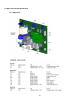
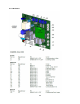
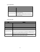
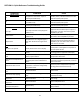

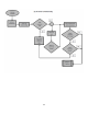
Table Of Contents
- Cover Page
- Section 0 (Table of Contents)
- Section 1 (Introduction)
- Section 2 (Sealed System)
- Section 3 (Sealed System Components)
- Section 4 (Electrical Component Access)
- Section 5 (User Interface Display)
- Section 6 (Control System)
- Section 7 (Lights, Doors, Drawer, and Hinges)
- Section 8 (Evaporator Compartment Access)
- Section 9 (Wiring Diagrams)
- Section 10 (Power On reset Mode)
- Section 11 (Quick Reference Troubleshooting)
- Section 12 (Diagnostic Flow Charts)
- Section 13 (Gathering Service Data)
- Section 14 (Beer Dispenser)
- Section 15 (Dual Zones)
- 15.1: User Interface Control
- 15.2: Operation
- 15.3: Characteristics
- 15.4: Dual Zone Compartment Air Flow
- 15.5: Divider Removal
- 15.6: Damper Operation
- 15.7: Compartment Fan Operation
- 15.8: Heater Operation
- 15.9: Thermistors
- 15.10: Evaporator Access
- 15.11: Interior LED’s
- 15.12: Defrost / Drip Time
- 15.13: Refrigeration and Mechanical
- Section 16 (Refrigerator Freezers)
- Section 17 (Outdoor Models)
- 17.1: Operation
- 17.2: Characteristics / Differences
- 17.3: Fans
- 17.4: Thermistors
- 17.5: Control Type
- 17.6 : Control Functions
- 17.7: Control Locations per Model
- 17.8: Machine Compartment
- 17.9: Main Power Board Access
- 17.10: Display Access and Replacement
- 17.11: Thermistor Resistance
- 17.12: Wiring Diagram
- 17.13: Generic Trouble shooting Charts
- 17.14: Refrigeration and Mechanical
- Section 18 (Prime Control)
- Section 19 (Clear Ice Machines)
- Section 20 (Service Kits / Bulletins)
- 20.1: Service Bulletin # 41013862Mullion Condensation on Refrigerated Drawers
- 20.2: SERVICE BULLETIN # 41013861EVAPORATOR REPLACEMENT KIT
- 20.3: SERVICE BULLETIN # 41013995 Rev CContact between the Door and Door Sensor
- 20.4: SERVICE BULLETIN # 41014167Slotted Condenser Shroud
- 20.5: SERVICE BULLETIN # 41014168Showroom Mode Alarm
- 20.6: SERVICE BULLETIN # 41014169Evaporator / Heat Exchanger Replacement(RF and RFI Models ONLY)
- 20.7: SERVICE BULLETIN # 41014241Shelf Shim Kit
- 20.8: Service Bulletin # 41014242Miscellaneous Control Communication Errors
- 20.9: Service Bulletin # 41014243Replacement of MP Door Skins
- Section 21 (Customer Service Contact Information)
- Section 22 (Notes)
- Back Page

90
10.3.1 SINGLE ZONE:
AUTO TEST MODE
LOAD
ENABLED
Condenser (AUX A)
On for 15 seconds then OFF. Pause 2 seconds
Evaporator
On for 15 seconds then OFF. Pause 2 seconds
AUX C
On for 15 seconds then OFF. Pause 2 seconds
Comp & Cond Fan ONLY
On for 5 minutes then exit AUTO-TEST and RETURN to
NORMAL OPERATION.
NOTE: If there is a "Call for Cooling", upon return to
normal operation, the compressor and condenser fan
will remain enabled.
10.3.2 DUAL ZONE:
AUTO TEST MODE
LOAD
ENABLED
Condenser (AUX A)
On for 15 seconds then OFF. Pause 2 seconds
Evaporator Fan A
On for 15 seconds then OFF. Pause 2 seconds
Evaporator Fan B
On for 15 seconds then OFF. Pause 2 seconds
Damper A
Completes one CLOSE/OPEN/CLOSE cycle then OFF. Pause 2 seconds
Damper B
Completes one CLOSE/OPEN/CLOSE cycle then OFF. Pause 2 seconds
AUX B
On for 15 seconds then OFF. Pause 2 seconds
AUX C
On for 15 seconds then OFF. Pause 2 seconds
Comp & Cond Fan ONLY
On for 5 minutes then exit AUTO-TEST and RETURN to NORMAL OPERATION.
NOTE: If there is a "Call for Cooling", upon return to normal operation, the
compressor and condenser fan will remain enabled.
NOTE
No two loads can be on at the same time. The previous load must be
completely “Off” before the next load is enabled.