
Service Manual
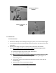
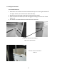
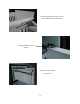
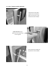
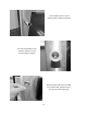
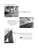
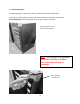
Table Of Contents
- Cover Page
- Section 0 (Table of Contents)
- Section 1 (Introduction)
- Section 2 (Sealed System)
- Section 3 (Sealed System Components)
- Section 4 (Electrical Component Access)
- Section 5 (User Interface Display)
- Section 6 (Control System)
- Section 7 (Lights, Doors, Drawer, and Hinges)
- Section 8 (Evaporator Compartment Access)
- Section 9 (Wiring Diagrams)
- Section 10 (Power On reset Mode)
- Section 11 (Quick Reference Troubleshooting)
- Section 12 (Diagnostic Flow Charts)
- Section 13 (Gathering Service Data)
- Section 14 (Beer Dispenser)
- Section 15 (Dual Zones)
- 15.1: User Interface Control
- 15.2: Operation
- 15.3: Characteristics
- 15.4: Dual Zone Compartment Air Flow
- 15.5: Divider Removal
- 15.6: Damper Operation
- 15.7: Compartment Fan Operation
- 15.8: Heater Operation
- 15.9: Thermistors
- 15.10: Evaporator Access
- 15.11: Interior LED’s
- 15.12: Defrost / Drip Time
- 15.13: Refrigeration and Mechanical
- Section 16 (Refrigerator Freezers)
- Section 17 (Outdoor Models)
- 17.1: Operation
- 17.2: Characteristics / Differences
- 17.3: Fans
- 17.4: Thermistors
- 17.5: Control Type
- 17.6 : Control Functions
- 17.7: Control Locations per Model
- 17.8: Machine Compartment
- 17.9: Main Power Board Access
- 17.10: Display Access and Replacement
- 17.11: Thermistor Resistance
- 17.12: Wiring Diagram
- 17.13: Generic Trouble shooting Charts
- 17.14: Refrigeration and Mechanical
- Section 18 (Prime Control)
- Section 19 (Clear Ice Machines)
- Section 20 (Service Kits / Bulletins)
- 20.1: Service Bulletin # 41013862Mullion Condensation on Refrigerated Drawers
- 20.2: SERVICE BULLETIN # 41013861EVAPORATOR REPLACEMENT KIT
- 20.3: SERVICE BULLETIN # 41013995 Rev CContact between the Door and Door Sensor
- 20.4: SERVICE BULLETIN # 41014167Slotted Condenser Shroud
- 20.5: SERVICE BULLETIN # 41014168Showroom Mode Alarm
- 20.6: SERVICE BULLETIN # 41014169Evaporator / Heat Exchanger Replacement(RF and RFI Models ONLY)
- 20.7: SERVICE BULLETIN # 41014241Shelf Shim Kit
- 20.8: Service Bulletin # 41014242Miscellaneous Control Communication Errors
- 20.9: Service Bulletin # 41014243Replacement of MP Door Skins
- Section 21 (Customer Service Contact Information)
- Section 22 (Notes)
- Back Page

66
Section 7: Lights, Doors, Drawers, and Hinges
7.1 LED Lighting
1. Refrigerated Drawers: are equipped with two LED lights. The upper LED is located on
the ceiling of the cabinet, while the lower LED is located on the underside of the mullion
assembly. These lights are controlled by the opening and closing of the associated
drawer. Each light is controlled by an independent rocker switch, which is located
behind each drawer on the back wall of the cabinet.
2. Beverage Centers: Have two LED lights and are located on the right hand and left hand
front of the cabinet ceiling.
3. Wine Coolers:
Single Zone: Have two LED lights which are located on the right hand and left
hand front of the cabinet ceiling.
Dual Zone: Same as the single zone with two additional LED lights on the center
divider in like positions as the cabinet ceiling.
The LED lighting for beverage centers and wine coolers is controlled both by the light switch on
the user interface display and also by the read switch mounted on the bottom flange of the
cabinet. Pressure from the door gasket makes and breaks the read switch circuitry to control
light function with door openings and closings.
Additional lighting features can be reviewed in the controls operation section in this manual.
7.1.1: Replacing the LED Light
1. Remove both Phillips screws in lens cover, the LED assembly can now be removed. (A
refrigerated drawer mullion is used for reference in below photo).
2. Disconnect the connector plug to replace LED.
3. Reverse process to install.
Refrigerated drawer mullion
shown in photo.