
Service Manual
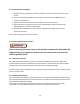
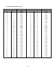
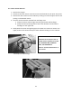
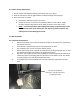
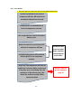
Table Of Contents
- Cover Page
- Section 0 (Table of Contents)
- Section 1 (Introduction)
- Section 2 (Sealed System)
- Section 3 (Sealed System Components)
- Section 4 (Electrical Component Access)
- Section 5 (User Interface Display)
- Section 6 (Control System)
- Section 7 (Lights, Doors, Drawer, and Hinges)
- Section 8 (Evaporator Compartment Access)
- Section 9 (Wiring Diagrams)
- Section 10 (Power On reset Mode)
- Section 11 (Quick Reference Troubleshooting)
- Section 12 (Diagnostic Flow Charts)
- Section 13 (Gathering Service Data)
- Section 14 (Beer Dispenser)
- Section 15 (Dual Zones)
- 15.1: User Interface Control
- 15.2: Operation
- 15.3: Characteristics
- 15.4: Dual Zone Compartment Air Flow
- 15.5: Divider Removal
- 15.6: Damper Operation
- 15.7: Compartment Fan Operation
- 15.8: Heater Operation
- 15.9: Thermistors
- 15.10: Evaporator Access
- 15.11: Interior LED’s
- 15.12: Defrost / Drip Time
- 15.13: Refrigeration and Mechanical
- Section 16 (Refrigerator Freezers)
- Section 17 (Outdoor Models)
- 17.1: Operation
- 17.2: Characteristics / Differences
- 17.3: Fans
- 17.4: Thermistors
- 17.5: Control Type
- 17.6 : Control Functions
- 17.7: Control Locations per Model
- 17.8: Machine Compartment
- 17.9: Main Power Board Access
- 17.10: Display Access and Replacement
- 17.11: Thermistor Resistance
- 17.12: Wiring Diagram
- 17.13: Generic Trouble shooting Charts
- 17.14: Refrigeration and Mechanical
- Section 18 (Prime Control)
- Section 19 (Clear Ice Machines)
- Section 20 (Service Kits / Bulletins)
- 20.1: Service Bulletin # 41013862Mullion Condensation on Refrigerated Drawers
- 20.2: SERVICE BULLETIN # 41013861EVAPORATOR REPLACEMENT KIT
- 20.3: SERVICE BULLETIN # 41013995 Rev CContact between the Door and Door Sensor
- 20.4: SERVICE BULLETIN # 41014167Slotted Condenser Shroud
- 20.5: SERVICE BULLETIN # 41014168Showroom Mode Alarm
- 20.6: SERVICE BULLETIN # 41014169Evaporator / Heat Exchanger Replacement(RF and RFI Models ONLY)
- 20.7: SERVICE BULLETIN # 41014241Shelf Shim Kit
- 20.8: Service Bulletin # 41014242Miscellaneous Control Communication Errors
- 20.9: Service Bulletin # 41014243Replacement of MP Door Skins
- Section 21 (Customer Service Contact Information)
- Section 22 (Notes)
- Back Page

65
Defrost Time Out (DTO) is the total time of compressor off time; including both defrost and
drip time cycles.
AS OF 8/1/15 THE FOLLOWING CHANGES WERE MADE TO THE DEFROST TIME OUT (DTO) ON
THE FOLLOWING MODELS:
On all models except for the RF, RI, DZ and ML24WS; the DTO was expanded from 60
to 75 minutes.
Model ML24WS was expanded from 40 to 75 minutes.
RF, RI, and DZ models remain the same.
6.6.3 Manual Defrost
A manual defrost can be activated by using the following sequence:
Press the LOCK and MINUS key simultaneously and hold for 3 seconds.
The display will flash dEF (defrost mode) three times before entering the
defrost mode.
dEF will be displayed for the duration of the defrost cycle.
The defrost cycles will terminate when either of the following conditions are
achieved first:
o the defrost has been active for 40 minutes
o the defrost thermistor reaches 40°F
6.7 Error Codes
With the Aurora control there are four error codes that could appear on the user interface
display. They are as follows:
EL : Compartment thermistor open or out of range
Ed : Defrost thermistor open or out of range
EL / Ed : Multiple thermistor errors, open or out of range
CE : Communication cable error, broken connector pin or wire