
Service Manual
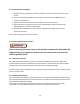
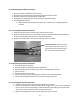
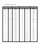
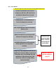
Table Of Contents
- Cover Page
- Section 0 (Table of Contents)
- Section 1 (Introduction)
- Section 2 (Sealed System)
- Section 3 (Sealed System Components)
- Section 4 (Electrical Component Access)
- Section 5 (User Interface Display)
- Section 6 (Control System)
- Section 7 (Lights, Doors, Drawer, and Hinges)
- Section 8 (Evaporator Compartment Access)
- Section 9 (Wiring Diagrams)
- Section 10 (Power On reset Mode)
- Section 11 (Quick Reference Troubleshooting)
- Section 12 (Diagnostic Flow Charts)
- Section 13 (Gathering Service Data)
- Section 14 (Beer Dispenser)
- Section 15 (Dual Zones)
- 15.1: User Interface Control
- 15.2: Operation
- 15.3: Characteristics
- 15.4: Dual Zone Compartment Air Flow
- 15.5: Divider Removal
- 15.6: Damper Operation
- 15.7: Compartment Fan Operation
- 15.8: Heater Operation
- 15.9: Thermistors
- 15.10: Evaporator Access
- 15.11: Interior LED’s
- 15.12: Defrost / Drip Time
- 15.13: Refrigeration and Mechanical
- Section 16 (Refrigerator Freezers)
- Section 17 (Outdoor Models)
- 17.1: Operation
- 17.2: Characteristics / Differences
- 17.3: Fans
- 17.4: Thermistors
- 17.5: Control Type
- 17.6 : Control Functions
- 17.7: Control Locations per Model
- 17.8: Machine Compartment
- 17.9: Main Power Board Access
- 17.10: Display Access and Replacement
- 17.11: Thermistor Resistance
- 17.12: Wiring Diagram
- 17.13: Generic Trouble shooting Charts
- 17.14: Refrigeration and Mechanical
- Section 18 (Prime Control)
- Section 19 (Clear Ice Machines)
- Section 20 (Service Kits / Bulletins)
- 20.1: Service Bulletin # 41013862Mullion Condensation on Refrigerated Drawers
- 20.2: SERVICE BULLETIN # 41013861EVAPORATOR REPLACEMENT KIT
- 20.3: SERVICE BULLETIN # 41013995 Rev CContact between the Door and Door Sensor
- 20.4: SERVICE BULLETIN # 41014167Slotted Condenser Shroud
- 20.5: SERVICE BULLETIN # 41014168Showroom Mode Alarm
- 20.6: SERVICE BULLETIN # 41014169Evaporator / Heat Exchanger Replacement(RF and RFI Models ONLY)
- 20.7: SERVICE BULLETIN # 41014241Shelf Shim Kit
- 20.8: Service Bulletin # 41014242Miscellaneous Control Communication Errors
- 20.9: Service Bulletin # 41014243Replacement of MP Door Skins
- Section 21 (Customer Service Contact Information)
- Section 22 (Notes)
- Back Page

64
6.6.2 Auto Defrost
Drip Time Reference: Dual Zone has been extended to 30 minutes.
Defrost is achieved as the result of
compressor off time. NO electrical or
mechanical alternatives are used.
Timed Defrost: is initiated every 6
hours of compressor run time.
The evaporator fan is on for the entire
defrost cycle.
Defrost is active for a period up to 40
minutes of compressor off time.
The defrost thermistor will terminate
defrost @ 40°F at its evaporator
location.
Drip Time: The compressor will have an
additional 2 minutes (30 for a dual zone)
of lag time prior to restarting after the
conclusion of the defrost cycle. This
allows the moisture to drip off the
evaporator plate.
The defrost will
terminate when
either condition
is achieved prior
to the other
Defrost Time Out
periods edited on
page 64