
Service Manual
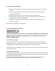
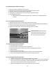
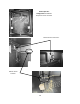
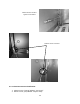
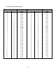
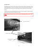
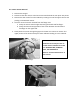
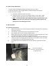
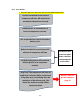
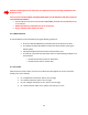
Table Of Contents
- Cover Page
- Section 0 (Table of Contents)
- Section 1 (Introduction)
- Section 2 (Sealed System)
- Section 3 (Sealed System Components)
- Section 4 (Electrical Component Access)
- Section 5 (User Interface Display)
- Section 6 (Control System)
- Section 7 (Lights, Doors, Drawer, and Hinges)
- Section 8 (Evaporator Compartment Access)
- Section 9 (Wiring Diagrams)
- Section 10 (Power On reset Mode)
- Section 11 (Quick Reference Troubleshooting)
- Section 12 (Diagnostic Flow Charts)
- Section 13 (Gathering Service Data)
- Section 14 (Beer Dispenser)
- Section 15 (Dual Zones)
- 15.1: User Interface Control
- 15.2: Operation
- 15.3: Characteristics
- 15.4: Dual Zone Compartment Air Flow
- 15.5: Divider Removal
- 15.6: Damper Operation
- 15.7: Compartment Fan Operation
- 15.8: Heater Operation
- 15.9: Thermistors
- 15.10: Evaporator Access
- 15.11: Interior LED’s
- 15.12: Defrost / Drip Time
- 15.13: Refrigeration and Mechanical
- Section 16 (Refrigerator Freezers)
- Section 17 (Outdoor Models)
- 17.1: Operation
- 17.2: Characteristics / Differences
- 17.3: Fans
- 17.4: Thermistors
- 17.5: Control Type
- 17.6 : Control Functions
- 17.7: Control Locations per Model
- 17.8: Machine Compartment
- 17.9: Main Power Board Access
- 17.10: Display Access and Replacement
- 17.11: Thermistor Resistance
- 17.12: Wiring Diagram
- 17.13: Generic Trouble shooting Charts
- 17.14: Refrigeration and Mechanical
- Section 18 (Prime Control)
- Section 19 (Clear Ice Machines)
- Section 20 (Service Kits / Bulletins)
- 20.1: Service Bulletin # 41013862Mullion Condensation on Refrigerated Drawers
- 20.2: SERVICE BULLETIN # 41013861EVAPORATOR REPLACEMENT KIT
- 20.3: SERVICE BULLETIN # 41013995 Rev CContact between the Door and Door Sensor
- 20.4: SERVICE BULLETIN # 41014167Slotted Condenser Shroud
- 20.5: SERVICE BULLETIN # 41014168Showroom Mode Alarm
- 20.6: SERVICE BULLETIN # 41014169Evaporator / Heat Exchanger Replacement(RF and RFI Models ONLY)
- 20.7: SERVICE BULLETIN # 41014241Shelf Shim Kit
- 20.8: Service Bulletin # 41014242Miscellaneous Control Communication Errors
- 20.9: Service Bulletin # 41014243Replacement of MP Door Skins
- Section 21 (Customer Service Contact Information)
- Section 22 (Notes)
- Back Page

57
6.3.3: Removing the Cabinet Thermistor
1. Remove interior shelving for ease of access.
2. Remove the decorative caps and screws from the thermistor shield.
3. Remove cantilever shelving brackets if applicable.
4. Disconnect the bad thermistor at the connector plug and remove.
5. For refrigerated drawers:
Remove both top and bottom drawers. See “section 7.4.1” regarding drawer
removal.
6.3.4: Installing the Cabinet Thermistor
1. Snap the new thermistor into the other half of the connector.
2. Place the new thermistor into its protective shield. The underneath side of the shield is
fitted to accommodate the grooves on the thermistor bulb.
3. Replace all components in the reverse order they were removed.
6.3.5: Removing the Defrost Thermistor
1. Remove all interior shelving.
2. Remove cantilever shelving brackets if applicable.
3. Remove decorative screw caps and screws from evaporator coil cover.
4. Disconnect fan.
5. Remove evaporator coil cover.
6. Cut the two nylon zip ties holding the thermistor to the evaporator plate.
7. Disconnect the bad thermistor at the connector plug and remove.
6.3.6: Installing the Defrost Thermistor
1. Snap the new thermistor into the other half of the connector.
2. Secure the thermistor on the evaporator plate using the two nylon zip ties included in
the kit. Insure that the thermistor is mounted with the bulb facing the left hand side
of the liner; pull the zip ties firmly for proper plate sense.
3. Replace all components in the reverse order they were removed.
Cabinet Thermistor: Note the locator
slot inside the thermistor shield. The
grooved thermistor bulb fits firmly in
the seat created inside the shield.