
Service Manual
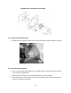
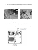
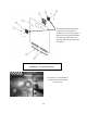
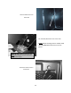
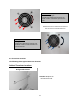
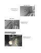
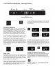
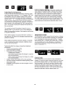
Table Of Contents
- Cover Page
- Section 0 (Table of Contents)
- Section 1 (Introduction)
- Section 2 (Sealed System)
- Section 3 (Sealed System Components)
- Section 4 (Electrical Component Access)
- Section 5 (User Interface Display)
- Section 6 (Control System)
- Section 7 (Lights, Doors, Drawer, and Hinges)
- Section 8 (Evaporator Compartment Access)
- Section 9 (Wiring Diagrams)
- Section 10 (Power On reset Mode)
- Section 11 (Quick Reference Troubleshooting)
- Section 12 (Diagnostic Flow Charts)
- Section 13 (Gathering Service Data)
- Section 14 (Beer Dispenser)
- Section 15 (Dual Zones)
- 15.1: User Interface Control
- 15.2: Operation
- 15.3: Characteristics
- 15.4: Dual Zone Compartment Air Flow
- 15.5: Divider Removal
- 15.6: Damper Operation
- 15.7: Compartment Fan Operation
- 15.8: Heater Operation
- 15.9: Thermistors
- 15.10: Evaporator Access
- 15.11: Interior LED’s
- 15.12: Defrost / Drip Time
- 15.13: Refrigeration and Mechanical
- Section 16 (Refrigerator Freezers)
- Section 17 (Outdoor Models)
- 17.1: Operation
- 17.2: Characteristics / Differences
- 17.3: Fans
- 17.4: Thermistors
- 17.5: Control Type
- 17.6 : Control Functions
- 17.7: Control Locations per Model
- 17.8: Machine Compartment
- 17.9: Main Power Board Access
- 17.10: Display Access and Replacement
- 17.11: Thermistor Resistance
- 17.12: Wiring Diagram
- 17.13: Generic Trouble shooting Charts
- 17.14: Refrigeration and Mechanical
- Section 18 (Prime Control)
- Section 19 (Clear Ice Machines)
- Section 20 (Service Kits / Bulletins)
- 20.1: Service Bulletin # 41013862Mullion Condensation on Refrigerated Drawers
- 20.2: SERVICE BULLETIN # 41013861EVAPORATOR REPLACEMENT KIT
- 20.3: SERVICE BULLETIN # 41013995 Rev CContact between the Door and Door Sensor
- 20.4: SERVICE BULLETIN # 41014167Slotted Condenser Shroud
- 20.5: SERVICE BULLETIN # 41014168Showroom Mode Alarm
- 20.6: SERVICE BULLETIN # 41014169Evaporator / Heat Exchanger Replacement(RF and RFI Models ONLY)
- 20.7: SERVICE BULLETIN # 41014241Shelf Shim Kit
- 20.8: Service Bulletin # 41014242Miscellaneous Control Communication Errors
- 20.9: Service Bulletin # 41014243Replacement of MP Door Skins
- Section 21 (Customer Service Contact Information)
- Section 22 (Notes)
- Back Page

28
4.2: Evaporator Fan Access
For all models, with the exception of the beer dispenser, the evaporator fan draws air from the
refrigerated space through the bottom supply air louvers, across the evaporator plate, and then
re-distributes it back into the cabinet through the fan itself.
The beer dispenser fan has reversed air flow. The evaporator fan is installed with the writing on
the motor hub facing the rear of the cabinet; this creates a draw through application, pushing
the air downward across the evaporator plate and out the bottom louvers on the evaporator
cover.
To access the evaporator fan, follow the steps below:
1. Remove all shelving.
2. Remove decorative plastic screw caps.
3. Remove screws around the perimeter of the back panel.
4. If the appliance has cantilever shelving, the rails will have to be removed to expose the
screw caps and screws securing the back panel.
5. Additionally with cantilever shelving the rear screw on thermistor shield will need to be
removed as the thermistor is fed through the cantilever bracket.
6. The back panel is slotted mid-way up on the left hand side. This is to accommodate the
thermistor.
7. The rear panel can now be removed.
8. The disconnect plug for the evaporator fan motor is located in the upper right hand
corner.
9. See note on page 28 regarding air flow direction.
NOTE: As of mid-August 2015, a rear fan guard was added to the fan assemblies on the
beverage center models. The fan guard is to eliminate the possibility of wires getting
caught in the fan blade from behind the coil cover.
The approximate serial number range is 20150824xxxH. This is an approximate date and
some variation may be seen in the field.
An exploded view on the following page shows the assembly drawing of the coil cover
components along with both the front and rear fan guards.