
Service Manual
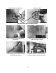
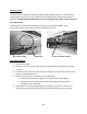
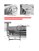
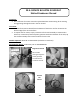
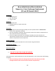
Table Of Contents
- Cover Page
- Section 0 (Table of Contents)
- Section 1 (Introduction)
- Section 2 (Sealed System)
- Section 3 (Sealed System Components)
- Section 4 (Electrical Component Access)
- Section 5 (User Interface Display)
- Section 6 (Control System)
- Section 7 (Lights, Doors, Drawer, and Hinges)
- Section 8 (Evaporator Compartment Access)
- Section 9 (Wiring Diagrams)
- Section 10 (Power On reset Mode)
- Section 11 (Quick Reference Troubleshooting)
- Section 12 (Diagnostic Flow Charts)
- Section 13 (Gathering Service Data)
- Section 14 (Beer Dispenser)
- Section 15 (Dual Zones)
- 15.1: User Interface Control
- 15.2: Operation
- 15.3: Characteristics
- 15.4: Dual Zone Compartment Air Flow
- 15.5: Divider Removal
- 15.6: Damper Operation
- 15.7: Compartment Fan Operation
- 15.8: Heater Operation
- 15.9: Thermistors
- 15.10: Evaporator Access
- 15.11: Interior LED’s
- 15.12: Defrost / Drip Time
- 15.13: Refrigeration and Mechanical
- Section 16 (Refrigerator Freezers)
- Section 17 (Outdoor Models)
- 17.1: Operation
- 17.2: Characteristics / Differences
- 17.3: Fans
- 17.4: Thermistors
- 17.5: Control Type
- 17.6 : Control Functions
- 17.7: Control Locations per Model
- 17.8: Machine Compartment
- 17.9: Main Power Board Access
- 17.10: Display Access and Replacement
- 17.11: Thermistor Resistance
- 17.12: Wiring Diagram
- 17.13: Generic Trouble shooting Charts
- 17.14: Refrigeration and Mechanical
- Section 18 (Prime Control)
- Section 19 (Clear Ice Machines)
- Section 20 (Service Kits / Bulletins)
- 20.1: Service Bulletin # 41013862Mullion Condensation on Refrigerated Drawers
- 20.2: SERVICE BULLETIN # 41013861EVAPORATOR REPLACEMENT KIT
- 20.3: SERVICE BULLETIN # 41013995 Rev CContact between the Door and Door Sensor
- 20.4: SERVICE BULLETIN # 41014167Slotted Condenser Shroud
- 20.5: SERVICE BULLETIN # 41014168Showroom Mode Alarm
- 20.6: SERVICE BULLETIN # 41014169Evaporator / Heat Exchanger Replacement(RF and RFI Models ONLY)
- 20.7: SERVICE BULLETIN # 41014241Shelf Shim Kit
- 20.8: Service Bulletin # 41014242Miscellaneous Control Communication Errors
- 20.9: Service Bulletin # 41014243Replacement of MP Door Skins
- Section 21 (Customer Service Contact Information)
- Section 22 (Notes)
- Back Page
257
Evaporator Installation
A replacement evaporator assembly (42249115) will include the following
components:
(1) Evaporator heat exchanger assembly
(1) Filter drier
(1) Pre bent suction tube extension
(1) Vibration isolator
(2) Nylon zip tie fasteners
(2) Pieces of permagum
1. Take the replacement evaporator and unroll the capillary tube on the heat exchanger.
2. Absolutely make sure that the ends of the capillary tube and suction line are well
capped. Wrap both ends with tape to insure that no foam enters the tubing when
passing through the ½” drilled hole. Any foam that is allowed in the tubing will
compromise the sealed system.
3. Once the new evaporator is in place, the suction line in the machine compartment will
have to be bent (thumbs and forefingers) at an angle towards the compressor.
4. Carefully recoil the capillary tube.
5. Install a new filter drier and solder the capillary and liquid line in place.
6. The kit will include a section of pre-bent suction line. The bent end will be soldered into
the compressor.
7. Use a 3/8”swedging tool to expand the opposite end of the suction extension. This will
fit over the new suction line extending into the machine compartment. This connection
can now be soldered.
8. The kit also includes a rubber vibration isolator, place this onto the heat exchanger
behind the evaporator to protect against tube rattles between the evaporator and
cabinet liner.
9. Replace the defrost thermistor and attach with the two zip lock fasteners in the kit.
10. Place one piece of permagum around the newly drilled hole for the suction line
assembly inside the interior of the cabinet. Make sure that it is worked into and around
the hole to seal off any moisture or heat.
11. Use the second piece of permagum and also work that into and around the hole in the
machine compartment where the new suction line assembly exits the liner.
12. Re-install the white foam spacers. The spacers have an off center cut on one side, place
the fat side of the spacer (with the thickest foam) towards the back wall of the liner.
13. Reassemble the coil cover and interior components in reverse order as removed.
14. Prior to reassembling the machine compartment, a thorough leak check should be
performed to verify that all joints have been soldered or brazed correctly.
15. Proceed to pull a minimum 50 Micro vacuum.
16. Recharge system with weighted charge per specification on serial plate.
17. Leak check.