
Service Manual
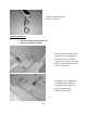
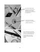
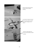
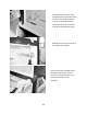
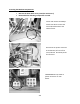
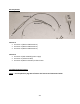
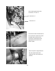
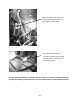
Table Of Contents
- Cover Page
- Section 0 (Table of Contents)
- Section 1 (Introduction)
- Section 2 (Sealed System)
- Section 3 (Sealed System Components)
- Section 4 (Electrical Component Access)
- Section 5 (User Interface Display)
- Section 6 (Control System)
- Section 7 (Lights, Doors, Drawer, and Hinges)
- Section 8 (Evaporator Compartment Access)
- Section 9 (Wiring Diagrams)
- Section 10 (Power On reset Mode)
- Section 11 (Quick Reference Troubleshooting)
- Section 12 (Diagnostic Flow Charts)
- Section 13 (Gathering Service Data)
- Section 14 (Beer Dispenser)
- Section 15 (Dual Zones)
- 15.1: User Interface Control
- 15.2: Operation
- 15.3: Characteristics
- 15.4: Dual Zone Compartment Air Flow
- 15.5: Divider Removal
- 15.6: Damper Operation
- 15.7: Compartment Fan Operation
- 15.8: Heater Operation
- 15.9: Thermistors
- 15.10: Evaporator Access
- 15.11: Interior LED’s
- 15.12: Defrost / Drip Time
- 15.13: Refrigeration and Mechanical
- Section 16 (Refrigerator Freezers)
- Section 17 (Outdoor Models)
- 17.1: Operation
- 17.2: Characteristics / Differences
- 17.3: Fans
- 17.4: Thermistors
- 17.5: Control Type
- 17.6 : Control Functions
- 17.7: Control Locations per Model
- 17.8: Machine Compartment
- 17.9: Main Power Board Access
- 17.10: Display Access and Replacement
- 17.11: Thermistor Resistance
- 17.12: Wiring Diagram
- 17.13: Generic Trouble shooting Charts
- 17.14: Refrigeration and Mechanical
- Section 18 (Prime Control)
- Section 19 (Clear Ice Machines)
- Section 20 (Service Kits / Bulletins)
- 20.1: Service Bulletin # 41013862Mullion Condensation on Refrigerated Drawers
- 20.2: SERVICE BULLETIN # 41013861EVAPORATOR REPLACEMENT KIT
- 20.3: SERVICE BULLETIN # 41013995 Rev CContact between the Door and Door Sensor
- 20.4: SERVICE BULLETIN # 41014167Slotted Condenser Shroud
- 20.5: SERVICE BULLETIN # 41014168Showroom Mode Alarm
- 20.6: SERVICE BULLETIN # 41014169Evaporator / Heat Exchanger Replacement(RF and RFI Models ONLY)
- 20.7: SERVICE BULLETIN # 41014241Shelf Shim Kit
- 20.8: Service Bulletin # 41014242Miscellaneous Control Communication Errors
- 20.9: Service Bulletin # 41014243Replacement of MP Door Skins
- Section 21 (Customer Service Contact Information)
- Section 22 (Notes)
- Back Page

255
20.2: SERVICE BULLETIN # 41013861
EVAPORATOR REPLACEMENT KIT*
*THIS KIT DOES NOT FIT THE RF / RFI MODELS, SEE THAT BULLETIN LATER
IN THIS SECTION
Part number: 42249115, Evaporator Kit with Installation Instructions
REFER TO SECTION 3.6 FOR ADDITIONAL DISASSEMBLY INFORMATION
Reclaim Refrigerant from Sealed System
Reclaim the refrigerant in the sealed system per EPA regulations
Evaporator Removal
The evaporator heat exchanger is foamed in place in the back cabinet wall.
1. Cut the heat exchanger at the point it enters the foamed cabinet (behind
evaporator plate).
2. The suction line will also have to be cut at the point where it enters the foamed
cabinet from the machine compartment.
3. Remove the white foam evaporator spacers. Save as they will be used for the new
evaporator assembly.
4. Remove the evaporator and discard, caution of sharp edges from the cut tubing.
5. Unsolder suction line from compressor and discard, again use caution of sharp
edges surrounding cut heat exchanger.
6. Unsolder the liquid and capillary lines from the filter drier.
7. Drill a ½” hole in the left hand corner of the drain sump as close to the side wall as
possible. The hole must extend into the machine compartment.
8. Remove any sharp burrs on the top of the machine compartment created by the
drill bit.