
Service Manual
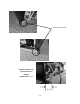
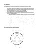
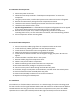
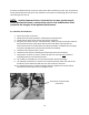
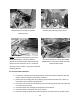
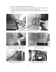
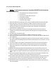
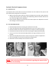
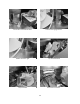
Table Of Contents
- Cover Page
- Section 0 (Table of Contents)
- Section 1 (Introduction)
- Section 2 (Sealed System)
- Section 3 (Sealed System Components)
- Section 4 (Electrical Component Access)
- Section 5 (User Interface Display)
- Section 6 (Control System)
- Section 7 (Lights, Doors, Drawer, and Hinges)
- Section 8 (Evaporator Compartment Access)
- Section 9 (Wiring Diagrams)
- Section 10 (Power On reset Mode)
- Section 11 (Quick Reference Troubleshooting)
- Section 12 (Diagnostic Flow Charts)
- Section 13 (Gathering Service Data)
- Section 14 (Beer Dispenser)
- Section 15 (Dual Zones)
- 15.1: User Interface Control
- 15.2: Operation
- 15.3: Characteristics
- 15.4: Dual Zone Compartment Air Flow
- 15.5: Divider Removal
- 15.6: Damper Operation
- 15.7: Compartment Fan Operation
- 15.8: Heater Operation
- 15.9: Thermistors
- 15.10: Evaporator Access
- 15.11: Interior LED’s
- 15.12: Defrost / Drip Time
- 15.13: Refrigeration and Mechanical
- Section 16 (Refrigerator Freezers)
- Section 17 (Outdoor Models)
- 17.1: Operation
- 17.2: Characteristics / Differences
- 17.3: Fans
- 17.4: Thermistors
- 17.5: Control Type
- 17.6 : Control Functions
- 17.7: Control Locations per Model
- 17.8: Machine Compartment
- 17.9: Main Power Board Access
- 17.10: Display Access and Replacement
- 17.11: Thermistor Resistance
- 17.12: Wiring Diagram
- 17.13: Generic Trouble shooting Charts
- 17.14: Refrigeration and Mechanical
- Section 18 (Prime Control)
- Section 19 (Clear Ice Machines)
- Section 20 (Service Kits / Bulletins)
- 20.1: Service Bulletin # 41013862Mullion Condensation on Refrigerated Drawers
- 20.2: SERVICE BULLETIN # 41013861EVAPORATOR REPLACEMENT KIT
- 20.3: SERVICE BULLETIN # 41013995 Rev CContact between the Door and Door Sensor
- 20.4: SERVICE BULLETIN # 41014167Slotted Condenser Shroud
- 20.5: SERVICE BULLETIN # 41014168Showroom Mode Alarm
- 20.6: SERVICE BULLETIN # 41014169Evaporator / Heat Exchanger Replacement(RF and RFI Models ONLY)
- 20.7: SERVICE BULLETIN # 41014241Shelf Shim Kit
- 20.8: Service Bulletin # 41014242Miscellaneous Control Communication Errors
- 20.9: Service Bulletin # 41014243Replacement of MP Door Skins
- Section 21 (Customer Service Contact Information)
- Section 22 (Notes)
- Back Page

21
7. Carefully reconnect all electrical terminals back on the terminal board.
8. Carefully push slide-in mechanical base plate assembly back under cabinet.
9. Secure base assembly to cabinet at rear and front locations.
10. Secure base assembly and toe grill.
3.6: Evaporator
The evaporator removes heat from the inside of the unit ultimately making the interior of the
appliance cold. The evaporator plate is flat in appearance (cold plate) and is installed behind
the coil cover.
It is normal for the evaporator to frost up during its run cycle. This frost will dissipate once the
unit reaches its “cut out” temperature and the compressor and fan stop. This condensate water
will drop off the evaporator plate and down into the tapered sump area formed in the cabinet.
The condensate will then drain down into the compressor condensate pan where it will
evaporate. It is very important that the evaporator frosts in a uniform pattern across the plate.
A partial frost pattern can lead to excessive run times and cooling issues.
Supply air is drawn across the evaporator plate from the evaporator fan and into the cabinet
interior through the supply louvers located at the bottom of the coil cover.
NOTE: Refer to Section 19 for a Service Bulletin regarding the removal of the
Evaporator / Heat Exchanger Assembly.
3.6.1: Remove the Evaporator
CAUTION Sharp burrs can result in cuts.
1. Disconnect power to the unit.
2. Use steps in Section 8 for access to evaporator compartment.
3. Follow the exact steps outlined in “Sealed System Components”.
4. Install sealed system access valves and recover refrigerant.
NOTE: The evaporator heat exchanger is foamed in place in the back
cabinet wall.
If an evaporator replacement is necessary, the heat exchanger will have to be cut at
the point it enters the foamed cabinet (behind evaporator plate). The suction line
will also have to be cut at the point where it enters the foamed cabinet from the
machine compartment.
5. Remove the white foam evaporator spacers. Save as they will be used for the new
evaporator assembly.
6. Remove the evaporator and discard, caution of sharp edges from the cut tubing.
7. Unsolder suction line from compressor and discard, again use caution of sharp edges
surrounding cut heat exchanger.