
Service Manual
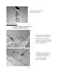
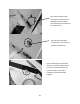
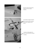
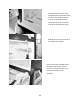
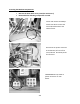
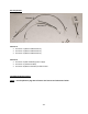
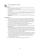
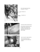
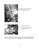
Table Of Contents
- Cover Page
- Section 0 (Table of Contents)
- Section 1 (Introduction)
- Section 2 (Sealed System)
- Section 3 (Sealed System Components)
- Section 4 (Electrical Component Access)
- Section 5 (User Interface Display)
- Section 6 (Control System)
- Section 7 (Lights, Doors, Drawer, and Hinges)
- Section 8 (Evaporator Compartment Access)
- Section 9 (Wiring Diagrams)
- Section 10 (Power On reset Mode)
- Section 11 (Quick Reference Troubleshooting)
- Section 12 (Diagnostic Flow Charts)
- Section 13 (Gathering Service Data)
- Section 14 (Beer Dispenser)
- Section 15 (Dual Zones)
- 15.1: User Interface Control
- 15.2: Operation
- 15.3: Characteristics
- 15.4: Dual Zone Compartment Air Flow
- 15.5: Divider Removal
- 15.6: Damper Operation
- 15.7: Compartment Fan Operation
- 15.8: Heater Operation
- 15.9: Thermistors
- 15.10: Evaporator Access
- 15.11: Interior LED’s
- 15.12: Defrost / Drip Time
- 15.13: Refrigeration and Mechanical
- Section 16 (Refrigerator Freezers)
- Section 17 (Outdoor Models)
- 17.1: Operation
- 17.2: Characteristics / Differences
- 17.3: Fans
- 17.4: Thermistors
- 17.5: Control Type
- 17.6 : Control Functions
- 17.7: Control Locations per Model
- 17.8: Machine Compartment
- 17.9: Main Power Board Access
- 17.10: Display Access and Replacement
- 17.11: Thermistor Resistance
- 17.12: Wiring Diagram
- 17.13: Generic Trouble shooting Charts
- 17.14: Refrigeration and Mechanical
- Section 18 (Prime Control)
- Section 19 (Clear Ice Machines)
- Section 20 (Service Kits / Bulletins)
- 20.1: Service Bulletin # 41013862Mullion Condensation on Refrigerated Drawers
- 20.2: SERVICE BULLETIN # 41013861EVAPORATOR REPLACEMENT KIT
- 20.3: SERVICE BULLETIN # 41013995 Rev CContact between the Door and Door Sensor
- 20.4: SERVICE BULLETIN # 41014167Slotted Condenser Shroud
- 20.5: SERVICE BULLETIN # 41014168Showroom Mode Alarm
- 20.6: SERVICE BULLETIN # 41014169Evaporator / Heat Exchanger Replacement(RF and RFI Models ONLY)
- 20.7: SERVICE BULLETIN # 41014241Shelf Shim Kit
- 20.8: Service Bulletin # 41014242Miscellaneous Control Communication Errors
- 20.9: Service Bulletin # 41014243Replacement of MP Door Skins
- Section 21 (Customer Service Contact Information)
- Section 22 (Notes)
- Back Page

252
NOTE: See the following photos for reference.
Wiring Harness A
1. Locate and remove the Phillip’s head screw which secures the main power board
mounting bracket to the cabinet frame.
2. Remove the power connector at the bottom, left rear of the main power board (see
above photo).
3. Plug connector “1” on harness A into the POWER terminal on the main power board.
4. Attach the original connector previously removed from the POWER terminal to
connector “2” on harness A.
5. Plug the remaining connector “3” into the adjoining terminal on the power supply
from the kit.
Wiring Harness B
1. Locate connector “4” on harness B. The wire will be identified as “Power Supply”.
Plug this connector into the remaining terminal on the power supply from the kit.
2. Locate the yellow and black harness extending through the upper, left hand corner
of the machine compartment. The connector will be marked as “Mullion Heater”.
The wire will be coiled and unplugged as seen in picture above.
3. Plug the coiled connector (step 2) into the matching yellow and black wire on
harness B, connector “6”. It is also marked as “Mullion Heater”.
4. The remaining connector “5” will be plugged into the “Aux C” terminal on the main
power board.
5. At this time, the paper can be peeled off the adhesive tape on the bottom of the
power supply. With the power supply in one hand, reach between the main power
board and the condenser fan and place the power supply in a position where it will
be out of the way. Press down on the power supply to adhere into place. The wires
can be routed over the top of the main power board.
6. Place the main power board mounting bracket back into position. Confirm that the
rear slot on the mounting bracket is secured by the positioning tab on the bottom of
the machine compartment. Take care not to pinch any wires during this step.
7. The main power board mounting bracket can now be re-secured to the cabinet
frame using the Phillip’s screw.
8. If necessary the wires can be secured together with a nylon wire tie.