
Service Manual
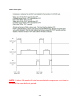
Table Of Contents
- Cover Page
- Section 0 (Table of Contents)
- Section 1 (Introduction)
- Section 2 (Sealed System)
- Section 3 (Sealed System Components)
- Section 4 (Electrical Component Access)
- Section 5 (User Interface Display)
- Section 6 (Control System)
- Section 7 (Lights, Doors, Drawer, and Hinges)
- Section 8 (Evaporator Compartment Access)
- Section 9 (Wiring Diagrams)
- Section 10 (Power On reset Mode)
- Section 11 (Quick Reference Troubleshooting)
- Section 12 (Diagnostic Flow Charts)
- Section 13 (Gathering Service Data)
- Section 14 (Beer Dispenser)
- Section 15 (Dual Zones)
- 15.1: User Interface Control
- 15.2: Operation
- 15.3: Characteristics
- 15.4: Dual Zone Compartment Air Flow
- 15.5: Divider Removal
- 15.6: Damper Operation
- 15.7: Compartment Fan Operation
- 15.8: Heater Operation
- 15.9: Thermistors
- 15.10: Evaporator Access
- 15.11: Interior LED’s
- 15.12: Defrost / Drip Time
- 15.13: Refrigeration and Mechanical
- Section 16 (Refrigerator Freezers)
- Section 17 (Outdoor Models)
- 17.1: Operation
- 17.2: Characteristics / Differences
- 17.3: Fans
- 17.4: Thermistors
- 17.5: Control Type
- 17.6 : Control Functions
- 17.7: Control Locations per Model
- 17.8: Machine Compartment
- 17.9: Main Power Board Access
- 17.10: Display Access and Replacement
- 17.11: Thermistor Resistance
- 17.12: Wiring Diagram
- 17.13: Generic Trouble shooting Charts
- 17.14: Refrigeration and Mechanical
- Section 18 (Prime Control)
- Section 19 (Clear Ice Machines)
- Section 20 (Service Kits / Bulletins)
- 20.1: Service Bulletin # 41013862Mullion Condensation on Refrigerated Drawers
- 20.2: SERVICE BULLETIN # 41013861EVAPORATOR REPLACEMENT KIT
- 20.3: SERVICE BULLETIN # 41013995 Rev CContact between the Door and Door Sensor
- 20.4: SERVICE BULLETIN # 41014167Slotted Condenser Shroud
- 20.5: SERVICE BULLETIN # 41014168Showroom Mode Alarm
- 20.6: SERVICE BULLETIN # 41014169Evaporator / Heat Exchanger Replacement(RF and RFI Models ONLY)
- 20.7: SERVICE BULLETIN # 41014241Shelf Shim Kit
- 20.8: Service Bulletin # 41014242Miscellaneous Control Communication Errors
- 20.9: Service Bulletin # 41014243Replacement of MP Door Skins
- Section 21 (Customer Service Contact Information)
- Section 22 (Notes)
- Back Page
239
Supply voltage to the ice machine will be interrupted if the drain pump
becomes full.
19.7.6 The Drain Pump is Inoperative:
1. Verify that the power cord is connected at the pump (2 locations) and the
main power board.
2. Look for possible restrictions in drain lines.
3. Ensure that the vent line is clear and able to breathe.
4. Not enough water to turn pump on.
a. At least 1 quart (.95 liters) of water is needed to activate the
pump.
19.7.7 The Drain Pump runs but not pumping:
1. Look for possible restrictions in drain lines.
2. Ensure that the vent line is clear and able to breathe.
3. Check to see if the drain line is to specifications.
a. Maximum lift is 8 feet (2.44 meters).
b. Maximum run is not greater than 20 feet (6.1 meters).
19.7.8 The Drain Pump runs momentarily and shuts off:
1. Ensure that the drain and vent lines are free and unrestricted.
2. Verify that the drain pump is level.
3. Look for loose voltage connections; inspect the power cord where it is
connected at the pump (2 locations) and the main power board.
19.7.9 Thermistor (Sensor) Error Detection:
Temperature thermistors are monitored continuously by the main power board. Any “OPEN,
SHORTED, or OUT of RANGE” thermistor circuit will initiate an alarm.
If an error is detected, the ice machine will immediately shut down and the display interface
will flash the corresponding fault code continuously. No audible alarm will sound.
19.7.10 Communication Error:
Loss of communication between the main power board and the user interface will result in
either a continually flashing “ON” or “OFF” on the display.