
Service Manual
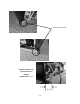
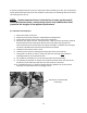
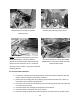
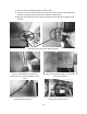
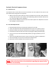
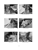
Table Of Contents
- Cover Page
- Section 0 (Table of Contents)
- Section 1 (Introduction)
- Section 2 (Sealed System)
- Section 3 (Sealed System Components)
- Section 4 (Electrical Component Access)
- Section 5 (User Interface Display)
- Section 6 (Control System)
- Section 7 (Lights, Doors, Drawer, and Hinges)
- Section 8 (Evaporator Compartment Access)
- Section 9 (Wiring Diagrams)
- Section 10 (Power On reset Mode)
- Section 11 (Quick Reference Troubleshooting)
- Section 12 (Diagnostic Flow Charts)
- Section 13 (Gathering Service Data)
- Section 14 (Beer Dispenser)
- Section 15 (Dual Zones)
- 15.1: User Interface Control
- 15.2: Operation
- 15.3: Characteristics
- 15.4: Dual Zone Compartment Air Flow
- 15.5: Divider Removal
- 15.6: Damper Operation
- 15.7: Compartment Fan Operation
- 15.8: Heater Operation
- 15.9: Thermistors
- 15.10: Evaporator Access
- 15.11: Interior LED’s
- 15.12: Defrost / Drip Time
- 15.13: Refrigeration and Mechanical
- Section 16 (Refrigerator Freezers)
- Section 17 (Outdoor Models)
- 17.1: Operation
- 17.2: Characteristics / Differences
- 17.3: Fans
- 17.4: Thermistors
- 17.5: Control Type
- 17.6 : Control Functions
- 17.7: Control Locations per Model
- 17.8: Machine Compartment
- 17.9: Main Power Board Access
- 17.10: Display Access and Replacement
- 17.11: Thermistor Resistance
- 17.12: Wiring Diagram
- 17.13: Generic Trouble shooting Charts
- 17.14: Refrigeration and Mechanical
- Section 18 (Prime Control)
- Section 19 (Clear Ice Machines)
- Section 20 (Service Kits / Bulletins)
- 20.1: Service Bulletin # 41013862Mullion Condensation on Refrigerated Drawers
- 20.2: SERVICE BULLETIN # 41013861EVAPORATOR REPLACEMENT KIT
- 20.3: SERVICE BULLETIN # 41013995 Rev CContact between the Door and Door Sensor
- 20.4: SERVICE BULLETIN # 41014167Slotted Condenser Shroud
- 20.5: SERVICE BULLETIN # 41014168Showroom Mode Alarm
- 20.6: SERVICE BULLETIN # 41014169Evaporator / Heat Exchanger Replacement(RF and RFI Models ONLY)
- 20.7: SERVICE BULLETIN # 41014241Shelf Shim Kit
- 20.8: Service Bulletin # 41014242Miscellaneous Control Communication Errors
- 20.9: Service Bulletin # 41014243Replacement of MP Door Skins
- Section 21 (Customer Service Contact Information)
- Section 22 (Notes)
- Back Page

19
A common problem with this system is restricted air flow caused by lint, dust, dirt, and pet hair.
These particles become built up on the condenser and results in overheating due to the lack of
sub-cooling across the coil.
NOTE: Another important factor is that the free air space on the toe grill
cannot be altered to meet a certain design criteria. Any modifications could
jeopardize the integrity of the appliance performance.
3.5.1: Remove the Condenser
1. Disconnect power to the unit.
2. Follow the exact steps outlined in “Sealed System Components”.
3. Install sealed system access valves and recover refrigerant.
4. Except for the “Data” and the “Communication” cable, all small connections must be
disconnected from the main power board. These two cables will stay with the
mechanical base and removed from the cabinet assembly. In addition the two larger
connectors DO NOT have to be disconnected from the board.
5. Unsolder and remove the filter / drier.
6. Unsolder and remove the discharge and liquid lines from the condenser.
7. Using a 3/8” nut driver or socket, remove (1) 3/8” nut securing each condenser
mounting bracket to the mechanical base.
8. The condenser assembly can now be removed from the base assembly.
9. Use a Phillips screwdriver to remove the condenser brackets from each side of the
condenser. The brackets will slide out once the screws are removed.
10. It is advisable that the un-soldered copper tubes be capped if the system will be
exposed to the atmosphere for any length of time.
Disconnect recommended
connectors.