
Service Manual
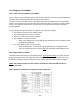
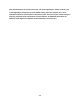
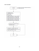
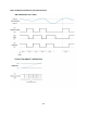
Table Of Contents
- Cover Page
- Section 0 (Table of Contents)
- Section 1 (Introduction)
- Section 2 (Sealed System)
- Section 3 (Sealed System Components)
- Section 4 (Electrical Component Access)
- Section 5 (User Interface Display)
- Section 6 (Control System)
- Section 7 (Lights, Doors, Drawer, and Hinges)
- Section 8 (Evaporator Compartment Access)
- Section 9 (Wiring Diagrams)
- Section 10 (Power On reset Mode)
- Section 11 (Quick Reference Troubleshooting)
- Section 12 (Diagnostic Flow Charts)
- Section 13 (Gathering Service Data)
- Section 14 (Beer Dispenser)
- Section 15 (Dual Zones)
- 15.1: User Interface Control
- 15.2: Operation
- 15.3: Characteristics
- 15.4: Dual Zone Compartment Air Flow
- 15.5: Divider Removal
- 15.6: Damper Operation
- 15.7: Compartment Fan Operation
- 15.8: Heater Operation
- 15.9: Thermistors
- 15.10: Evaporator Access
- 15.11: Interior LED’s
- 15.12: Defrost / Drip Time
- 15.13: Refrigeration and Mechanical
- Section 16 (Refrigerator Freezers)
- Section 17 (Outdoor Models)
- 17.1: Operation
- 17.2: Characteristics / Differences
- 17.3: Fans
- 17.4: Thermistors
- 17.5: Control Type
- 17.6 : Control Functions
- 17.7: Control Locations per Model
- 17.8: Machine Compartment
- 17.9: Main Power Board Access
- 17.10: Display Access and Replacement
- 17.11: Thermistor Resistance
- 17.12: Wiring Diagram
- 17.13: Generic Trouble shooting Charts
- 17.14: Refrigeration and Mechanical
- Section 18 (Prime Control)
- Section 19 (Clear Ice Machines)
- Section 20 (Service Kits / Bulletins)
- 20.1: Service Bulletin # 41013862Mullion Condensation on Refrigerated Drawers
- 20.2: SERVICE BULLETIN # 41013861EVAPORATOR REPLACEMENT KIT
- 20.3: SERVICE BULLETIN # 41013995 Rev CContact between the Door and Door Sensor
- 20.4: SERVICE BULLETIN # 41014167Slotted Condenser Shroud
- 20.5: SERVICE BULLETIN # 41014168Showroom Mode Alarm
- 20.6: SERVICE BULLETIN # 41014169Evaporator / Heat Exchanger Replacement(RF and RFI Models ONLY)
- 20.7: SERVICE BULLETIN # 41014241Shelf Shim Kit
- 20.8: Service Bulletin # 41014242Miscellaneous Control Communication Errors
- 20.9: Service Bulletin # 41014243Replacement of MP Door Skins
- Section 21 (Customer Service Contact Information)
- Section 22 (Notes)
- Back Page

229
19.5: Diagnostic Test Modes
19.5.1 Power on Reset (POR) Auto Test Mode:
Every “power on reset” (POR) will initiate with an “auto self-test”. The user interface display will
simulate normal operating conditions during the auto self-test.
This auto self-test mode will initiate at the beginning of the initial appliance start-up and after
power is restored after every loss of power that might occur due to customer or supply voltage
reasons. This function could result in a service call, so it’s possible that customer education
could be applied.
During the POR auto self-test mode, the appliance will operate as follows:
The display will show the last machine state.
The interior lights will function normally.
The “Lock” feature will function normally.
The “ON/OFF” key works normally.
o NOTE: if the appliance is turned “Off” during the POR self-test, the appliance will
be disabled immediately.
The “Delay Start” feature works normally.
o NOTE: if “Delay Start” is selected during the POR self-test, the appliance will
enter the selected delay start setting after the completion of the POR self-test.
19.5.2 Manual Auto Test Mode:
The manual auto test mode is activated manually by pressing and holding the “LOCK” key then
pressing the “Delay Start” key (again still while manually pressing and holding the “Lock” key).
The display will flash 5 times to indicate that the manual auto test mode has been enabled.
NOTE: The execution of the auto test sequence is identical in either the POR auto test or
manual test mode.
19.5.3 Appliance Component Test Sequence while in Auto Test: