
Service Manual
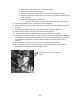
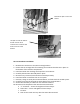
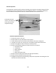
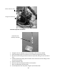
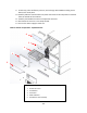
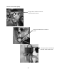
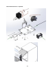
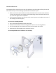
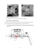
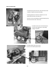
Table Of Contents
- Cover Page
- Section 0 (Table of Contents)
- Section 1 (Introduction)
- Section 2 (Sealed System)
- Section 3 (Sealed System Components)
- Section 4 (Electrical Component Access)
- Section 5 (User Interface Display)
- Section 6 (Control System)
- Section 7 (Lights, Doors, Drawer, and Hinges)
- Section 8 (Evaporator Compartment Access)
- Section 9 (Wiring Diagrams)
- Section 10 (Power On reset Mode)
- Section 11 (Quick Reference Troubleshooting)
- Section 12 (Diagnostic Flow Charts)
- Section 13 (Gathering Service Data)
- Section 14 (Beer Dispenser)
- Section 15 (Dual Zones)
- 15.1: User Interface Control
- 15.2: Operation
- 15.3: Characteristics
- 15.4: Dual Zone Compartment Air Flow
- 15.5: Divider Removal
- 15.6: Damper Operation
- 15.7: Compartment Fan Operation
- 15.8: Heater Operation
- 15.9: Thermistors
- 15.10: Evaporator Access
- 15.11: Interior LED’s
- 15.12: Defrost / Drip Time
- 15.13: Refrigeration and Mechanical
- Section 16 (Refrigerator Freezers)
- Section 17 (Outdoor Models)
- 17.1: Operation
- 17.2: Characteristics / Differences
- 17.3: Fans
- 17.4: Thermistors
- 17.5: Control Type
- 17.6 : Control Functions
- 17.7: Control Locations per Model
- 17.8: Machine Compartment
- 17.9: Main Power Board Access
- 17.10: Display Access and Replacement
- 17.11: Thermistor Resistance
- 17.12: Wiring Diagram
- 17.13: Generic Trouble shooting Charts
- 17.14: Refrigeration and Mechanical
- Section 18 (Prime Control)
- Section 19 (Clear Ice Machines)
- Section 20 (Service Kits / Bulletins)
- 20.1: Service Bulletin # 41013862Mullion Condensation on Refrigerated Drawers
- 20.2: SERVICE BULLETIN # 41013861EVAPORATOR REPLACEMENT KIT
- 20.3: SERVICE BULLETIN # 41013995 Rev CContact between the Door and Door Sensor
- 20.4: SERVICE BULLETIN # 41014167Slotted Condenser Shroud
- 20.5: SERVICE BULLETIN # 41014168Showroom Mode Alarm
- 20.6: SERVICE BULLETIN # 41014169Evaporator / Heat Exchanger Replacement(RF and RFI Models ONLY)
- 20.7: SERVICE BULLETIN # 41014241Shelf Shim Kit
- 20.8: Service Bulletin # 41014242Miscellaneous Control Communication Errors
- 20.9: Service Bulletin # 41014243Replacement of MP Door Skins
- Section 21 (Customer Service Contact Information)
- Section 22 (Notes)
- Back Page

216
Remove both upper and lower, rear access panels.
Disconnect the door sensor switch.
Remove the toe grill and access panel from the front of the machine.
Remove screws from all four corners that secure the cabinet assembly to the
base assembly.
Remove these following components:
i. Fill valve, drain valve, “Y” drain connection, and door sensor switch.
5. Install sealed system access valves and recover refrigerant.
6. Disconnect and cap the suction line from the compressor and the capillary tube from
the drier.
7. Slowly slide mechanical base assembly out from the rear of the appliance.
8. Disconnect any electrical harness that restricts your progress.
9. Unsolder and remove the discharge and liquid lines from the condenser.
10. Using a 3/8” nut driver or socket, remove (1) 3/8” nut securing the outside condenser
mounting bracket to the mechanical base. The inner mounting bracket can remain, as
the condenser should slide in and out with the bracket remaining in its current
position.
11. The condenser assembly can now be removed from the base assembly.
12. It is advisable that the un-soldered copper tubes be capped if the system will be
exposed to the atmosphere for any length of time.
Unsolder the condenser at these two
points.