
Service Manual
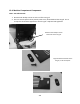
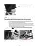
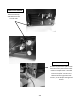
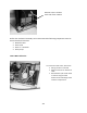
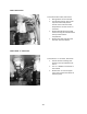
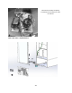
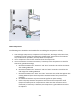
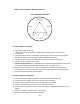
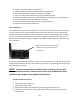
Table Of Contents
- Cover Page
- Section 0 (Table of Contents)
- Section 1 (Introduction)
- Section 2 (Sealed System)
- Section 3 (Sealed System Components)
- Section 4 (Electrical Component Access)
- Section 5 (User Interface Display)
- Section 6 (Control System)
- Section 7 (Lights, Doors, Drawer, and Hinges)
- Section 8 (Evaporator Compartment Access)
- Section 9 (Wiring Diagrams)
- Section 10 (Power On reset Mode)
- Section 11 (Quick Reference Troubleshooting)
- Section 12 (Diagnostic Flow Charts)
- Section 13 (Gathering Service Data)
- Section 14 (Beer Dispenser)
- Section 15 (Dual Zones)
- 15.1: User Interface Control
- 15.2: Operation
- 15.3: Characteristics
- 15.4: Dual Zone Compartment Air Flow
- 15.5: Divider Removal
- 15.6: Damper Operation
- 15.7: Compartment Fan Operation
- 15.8: Heater Operation
- 15.9: Thermistors
- 15.10: Evaporator Access
- 15.11: Interior LED’s
- 15.12: Defrost / Drip Time
- 15.13: Refrigeration and Mechanical
- Section 16 (Refrigerator Freezers)
- Section 17 (Outdoor Models)
- 17.1: Operation
- 17.2: Characteristics / Differences
- 17.3: Fans
- 17.4: Thermistors
- 17.5: Control Type
- 17.6 : Control Functions
- 17.7: Control Locations per Model
- 17.8: Machine Compartment
- 17.9: Main Power Board Access
- 17.10: Display Access and Replacement
- 17.11: Thermistor Resistance
- 17.12: Wiring Diagram
- 17.13: Generic Trouble shooting Charts
- 17.14: Refrigeration and Mechanical
- Section 18 (Prime Control)
- Section 19 (Clear Ice Machines)
- Section 20 (Service Kits / Bulletins)
- 20.1: Service Bulletin # 41013862Mullion Condensation on Refrigerated Drawers
- 20.2: SERVICE BULLETIN # 41013861EVAPORATOR REPLACEMENT KIT
- 20.3: SERVICE BULLETIN # 41013995 Rev CContact between the Door and Door Sensor
- 20.4: SERVICE BULLETIN # 41014167Slotted Condenser Shroud
- 20.5: SERVICE BULLETIN # 41014168Showroom Mode Alarm
- 20.6: SERVICE BULLETIN # 41014169Evaporator / Heat Exchanger Replacement(RF and RFI Models ONLY)
- 20.7: SERVICE BULLETIN # 41014241Shelf Shim Kit
- 20.8: Service Bulletin # 41014242Miscellaneous Control Communication Errors
- 20.9: Service Bulletin # 41014243Replacement of MP Door Skins
- Section 21 (Customer Service Contact Information)
- Section 22 (Notes)
- Back Page

215
8. Solder a new process tube to compressor.
9. Solder the discharge and suction lines back into compressor.
10. Re-install TSD2 starter package to compressor terminals.
11. Connect service ports to both the high and low sides of system.
12. Evacuate, charge to serial plate recommendation, and leak check the sealed system.
13. Push the mechanical base assembly back into place.
14. Secure base assembly to cabinet at rear and front locations.
15. Replace the front grill and back panel.
19.4.9 Condenser:
The condenser is of tube and wire construction. It is draw through; forced air technology used
for heat transfer. The front grill facilitates both intake and exhaust air. Inlet air passes both
through the toe grill and above the louvered section on the front access panel. The condenser
sets in an enclosure that prevents air recirculation. Exhaust air passes over the main control
board and out through the toe grill. A baffle on the appliance door also aids in preventing any
air recirculation.
A common problem with this system is restricted air flow caused by lint, dust, dirt, and pet hair.
These particles become built up on the condenser and results in overheating due to the lack of
sub-cooling across the coil.
NOTE: Another important factor is that the free air space on the toe grill
cannot be altered to meet a certain design criteria. Any modifications could
jeopardize the integrity of the appliance performance.
19.4.9.1 Condenser Removal
1. Disconnect power to the unit.
2. Shut off the supply water.
3. Disconnect the drain line and drain any remaining water from the line.
4. Follow these steps to ease in the removal of the base assembly from the machine
compartment.
Baffle on the inside, lower door of the
appliance helps prevent possible air
recirculation.