
Service Manual
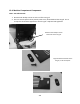
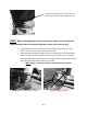
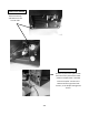
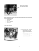
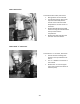
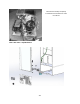
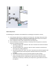
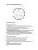
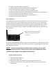
Table Of Contents
- Cover Page
- Section 0 (Table of Contents)
- Section 1 (Introduction)
- Section 2 (Sealed System)
- Section 3 (Sealed System Components)
- Section 4 (Electrical Component Access)
- Section 5 (User Interface Display)
- Section 6 (Control System)
- Section 7 (Lights, Doors, Drawer, and Hinges)
- Section 8 (Evaporator Compartment Access)
- Section 9 (Wiring Diagrams)
- Section 10 (Power On reset Mode)
- Section 11 (Quick Reference Troubleshooting)
- Section 12 (Diagnostic Flow Charts)
- Section 13 (Gathering Service Data)
- Section 14 (Beer Dispenser)
- Section 15 (Dual Zones)
- 15.1: User Interface Control
- 15.2: Operation
- 15.3: Characteristics
- 15.4: Dual Zone Compartment Air Flow
- 15.5: Divider Removal
- 15.6: Damper Operation
- 15.7: Compartment Fan Operation
- 15.8: Heater Operation
- 15.9: Thermistors
- 15.10: Evaporator Access
- 15.11: Interior LED’s
- 15.12: Defrost / Drip Time
- 15.13: Refrigeration and Mechanical
- Section 16 (Refrigerator Freezers)
- Section 17 (Outdoor Models)
- 17.1: Operation
- 17.2: Characteristics / Differences
- 17.3: Fans
- 17.4: Thermistors
- 17.5: Control Type
- 17.6 : Control Functions
- 17.7: Control Locations per Model
- 17.8: Machine Compartment
- 17.9: Main Power Board Access
- 17.10: Display Access and Replacement
- 17.11: Thermistor Resistance
- 17.12: Wiring Diagram
- 17.13: Generic Trouble shooting Charts
- 17.14: Refrigeration and Mechanical
- Section 18 (Prime Control)
- Section 19 (Clear Ice Machines)
- Section 20 (Service Kits / Bulletins)
- 20.1: Service Bulletin # 41013862Mullion Condensation on Refrigerated Drawers
- 20.2: SERVICE BULLETIN # 41013861EVAPORATOR REPLACEMENT KIT
- 20.3: SERVICE BULLETIN # 41013995 Rev CContact between the Door and Door Sensor
- 20.4: SERVICE BULLETIN # 41014167Slotted Condenser Shroud
- 20.5: SERVICE BULLETIN # 41014168Showroom Mode Alarm
- 20.6: SERVICE BULLETIN # 41014169Evaporator / Heat Exchanger Replacement(RF and RFI Models ONLY)
- 20.7: SERVICE BULLETIN # 41014241Shelf Shim Kit
- 20.8: Service Bulletin # 41014242Miscellaneous Control Communication Errors
- 20.9: Service Bulletin # 41014243Replacement of MP Door Skins
- Section 21 (Customer Service Contact Information)
- Section 22 (Notes)
- Back Page

214
19.4.8.1 Check Compressor Winding Resistance:
19.4.8.2 Compressor Removal
1. Disconnect power to the unit.
2. Follow the exact steps outlined in “Sealed System Components” to access the
compressor.
3. Using the process tubes, install sealed system access valves and recover refrigerant.
4. Remove the TSD2 starter package from the compressor terminals.
5. Unsolder and remove the discharge and suction lines from the compressor.
6. Unsolder and remove the filter / drier.
7. Cap all refrigeration lines: It is advisable that all exposed refrigeration lines be capped
if the system will be exposed to the atmosphere for any length of time.
8. Remove the three 7/16” nuts, washers and grounding screw(s) from compressor
mounting bolts. There is no nut and washer at the back, left hand mounting position.
9. Lift the compressor off the mounting bolts.
19.4.8.3 Compressor Installation
1. Do not remove the rubber plugs from the compressor tubes at this time.
2. Install the four (4) rubber grommets onto the compressor base.
3. Install the three (3) sleeves where the carriage bolts are located.
4. Mount the compressor into position on the mechanical base.
5. Install the three (3) washers and lock nuts and tighten snuggly into place. Do not over
tighten.
6. Install and solder a new filter drier in the system.
7. Remove rubber plugs from compressor tubes.