
Service Manual
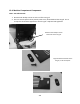
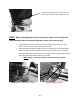
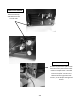
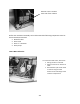
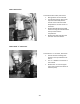
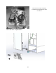
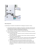
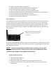
Table Of Contents
- Cover Page
- Section 0 (Table of Contents)
- Section 1 (Introduction)
- Section 2 (Sealed System)
- Section 3 (Sealed System Components)
- Section 4 (Electrical Component Access)
- Section 5 (User Interface Display)
- Section 6 (Control System)
- Section 7 (Lights, Doors, Drawer, and Hinges)
- Section 8 (Evaporator Compartment Access)
- Section 9 (Wiring Diagrams)
- Section 10 (Power On reset Mode)
- Section 11 (Quick Reference Troubleshooting)
- Section 12 (Diagnostic Flow Charts)
- Section 13 (Gathering Service Data)
- Section 14 (Beer Dispenser)
- Section 15 (Dual Zones)
- 15.1: User Interface Control
- 15.2: Operation
- 15.3: Characteristics
- 15.4: Dual Zone Compartment Air Flow
- 15.5: Divider Removal
- 15.6: Damper Operation
- 15.7: Compartment Fan Operation
- 15.8: Heater Operation
- 15.9: Thermistors
- 15.10: Evaporator Access
- 15.11: Interior LED’s
- 15.12: Defrost / Drip Time
- 15.13: Refrigeration and Mechanical
- Section 16 (Refrigerator Freezers)
- Section 17 (Outdoor Models)
- 17.1: Operation
- 17.2: Characteristics / Differences
- 17.3: Fans
- 17.4: Thermistors
- 17.5: Control Type
- 17.6 : Control Functions
- 17.7: Control Locations per Model
- 17.8: Machine Compartment
- 17.9: Main Power Board Access
- 17.10: Display Access and Replacement
- 17.11: Thermistor Resistance
- 17.12: Wiring Diagram
- 17.13: Generic Trouble shooting Charts
- 17.14: Refrigeration and Mechanical
- Section 18 (Prime Control)
- Section 19 (Clear Ice Machines)
- Section 20 (Service Kits / Bulletins)
- 20.1: Service Bulletin # 41013862Mullion Condensation on Refrigerated Drawers
- 20.2: SERVICE BULLETIN # 41013861EVAPORATOR REPLACEMENT KIT
- 20.3: SERVICE BULLETIN # 41013995 Rev CContact between the Door and Door Sensor
- 20.4: SERVICE BULLETIN # 41014167Slotted Condenser Shroud
- 20.5: SERVICE BULLETIN # 41014168Showroom Mode Alarm
- 20.6: SERVICE BULLETIN # 41014169Evaporator / Heat Exchanger Replacement(RF and RFI Models ONLY)
- 20.7: SERVICE BULLETIN # 41014241Shelf Shim Kit
- 20.8: Service Bulletin # 41014242Miscellaneous Control Communication Errors
- 20.9: Service Bulletin # 41014243Replacement of MP Door Skins
- Section 21 (Customer Service Contact Information)
- Section 22 (Notes)
- Back Page

208
19.4.2 Warnings and Cautions:
WARNING
Prior to removing the access cover to the machine compartment, disconnect the
supply voltage to the appliance. Failure to do this could result in an electrical
shock or possible death.
CAUTION
All electrical parts and wiring must be shielded from torch flame. DO NOT allow
torch to touch insulation; the insulation will char at 200°F and flash ignite (burn)
at 500°F. Excessive heat will distort the plastic liner.
19.4.3 Mechanical Compartment:
WARNING: The refrigeration system must be evacuated prior to unsoldering the
compressor or any other system related component.
Access to the mechanical compartment is located at the rear of the unit. Most mechanical and
electrical components on the unit mount directly to the slide out base.
To gain access to the mechanical section proceed as follows; be sure to reference the photos as
called out.
1. For access to the machine compartment remove the screws securing the bottom
compartment panel at the rear of the cabinet.
2. For additional service needs, it may be necessary to slide the machine compartment
assembly out. Proceed with the following steps.
Remove the rear, upper access panel.
Back out the two Phillips screws (1 on each side) on the toe grill.
Once the toe grill is removed, it will be necessary to remove all four screws
(two on each side) to loosen the mechanical assembly from the front.
At the rear bottom corner of the unit two (1 on each side) 5/16” hex head
screws can be removed.
3. The mechanical section can now be slid out no more than 8 - 10” maximum until the
suction line has been unsoldered from the compressor.
CAUTION: To avoid kinking the suction line assembly - do not slide the
mechanical base outward past the 8-10” maximum recommended above.
4. To change the HGV or condenser it is necessary to evacuate and reclaim the
refrigerant from the system prior to this step.