
Service Manual
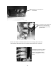
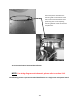
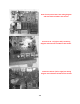
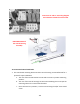
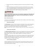
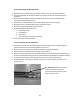
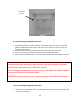
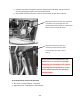
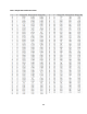
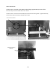
Table Of Contents
- Cover Page
- Section 0 (Table of Contents)
- Section 1 (Introduction)
- Section 2 (Sealed System)
- Section 3 (Sealed System Components)
- Section 4 (Electrical Component Access)
- Section 5 (User Interface Display)
- Section 6 (Control System)
- Section 7 (Lights, Doors, Drawer, and Hinges)
- Section 8 (Evaporator Compartment Access)
- Section 9 (Wiring Diagrams)
- Section 10 (Power On reset Mode)
- Section 11 (Quick Reference Troubleshooting)
- Section 12 (Diagnostic Flow Charts)
- Section 13 (Gathering Service Data)
- Section 14 (Beer Dispenser)
- Section 15 (Dual Zones)
- 15.1: User Interface Control
- 15.2: Operation
- 15.3: Characteristics
- 15.4: Dual Zone Compartment Air Flow
- 15.5: Divider Removal
- 15.6: Damper Operation
- 15.7: Compartment Fan Operation
- 15.8: Heater Operation
- 15.9: Thermistors
- 15.10: Evaporator Access
- 15.11: Interior LED’s
- 15.12: Defrost / Drip Time
- 15.13: Refrigeration and Mechanical
- Section 16 (Refrigerator Freezers)
- Section 17 (Outdoor Models)
- 17.1: Operation
- 17.2: Characteristics / Differences
- 17.3: Fans
- 17.4: Thermistors
- 17.5: Control Type
- 17.6 : Control Functions
- 17.7: Control Locations per Model
- 17.8: Machine Compartment
- 17.9: Main Power Board Access
- 17.10: Display Access and Replacement
- 17.11: Thermistor Resistance
- 17.12: Wiring Diagram
- 17.13: Generic Trouble shooting Charts
- 17.14: Refrigeration and Mechanical
- Section 18 (Prime Control)
- Section 19 (Clear Ice Machines)
- Section 20 (Service Kits / Bulletins)
- 20.1: Service Bulletin # 41013862Mullion Condensation on Refrigerated Drawers
- 20.2: SERVICE BULLETIN # 41013861EVAPORATOR REPLACEMENT KIT
- 20.3: SERVICE BULLETIN # 41013995 Rev CContact between the Door and Door Sensor
- 20.4: SERVICE BULLETIN # 41014167Slotted Condenser Shroud
- 20.5: SERVICE BULLETIN # 41014168Showroom Mode Alarm
- 20.6: SERVICE BULLETIN # 41014169Evaporator / Heat Exchanger Replacement(RF and RFI Models ONLY)
- 20.7: SERVICE BULLETIN # 41014241Shelf Shim Kit
- 20.8: Service Bulletin # 41014242Miscellaneous Control Communication Errors
- 20.9: Service Bulletin # 41014243Replacement of MP Door Skins
- Section 21 (Customer Service Contact Information)
- Section 22 (Notes)
- Back Page

190
2. Replace all previously removed wiring connectors to the correct location on the main
board.
3. Prior to reinstalling the control board, verify that the slotted tabs on the rear of the
control mounting board glide into their adjoining locator slots on the control housing.
4. Slide the assembly into position and secure with the 5/16” sheet metal screw.
5. Replace the center mullion, lower access panel, toe grill, and door.
WARNING
Prior to removing the access cover to the machine compartment, disconnect the
supply voltage to the appliance. Failure to do this could result in an electrical
shock or possible death.
19.2.3 Thermistor (Sensor):
Thermistors can be checked by use of a multi-meter with the ability to read resistance. Refer to
the resistance chart on page 191.
19.2.3.1 Bin Thermistor
The bin thermistor senses the interior temperature allowing the control to adjust and properly
display the interior temperature. The thermistor is located at the mid, left hand wall. The
thermistor is covered with a plastic shield to prevent accidental damage.
The bin thermistor looks to “Start” a production mode at 43°F and to “Stop” ice production at
37°F.
19.2.3.2 System Thermistor
The high side (System) thermistor senses the system temperature at the filter drier inlet (liquid
line). Higher temperature variations will have a negative effect on ice production. Possible
effects could be caused by a higher ambient temperature or possibly a condenser air
restriction.
To account for these changes, the main control board is programmed to compensate by either
adding or subtracting a factor to the compressor “On Time” for every 1°F change the system
thermistor senses in temperature change. This adjustment will ensure that the ice maker
continues to produce a suitable amount of ice.
19.2.3.3 Checking Thermistors
The bin and high side thermistor harnesses from the control board are foamed in place. The
recommended method to ohm the thermistor is to remove the thermistor connector at the
control board and take the reading.