
Service Manual
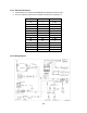
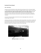
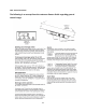
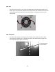
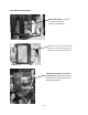
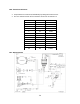
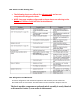
Table Of Contents
- Cover Page
- Section 0 (Table of Contents)
- Section 1 (Introduction)
- Section 2 (Sealed System)
- Section 3 (Sealed System Components)
- Section 4 (Electrical Component Access)
- Section 5 (User Interface Display)
- Section 6 (Control System)
- Section 7 (Lights, Doors, Drawer, and Hinges)
- Section 8 (Evaporator Compartment Access)
- Section 9 (Wiring Diagrams)
- Section 10 (Power On reset Mode)
- Section 11 (Quick Reference Troubleshooting)
- Section 12 (Diagnostic Flow Charts)
- Section 13 (Gathering Service Data)
- Section 14 (Beer Dispenser)
- Section 15 (Dual Zones)
- 15.1: User Interface Control
- 15.2: Operation
- 15.3: Characteristics
- 15.4: Dual Zone Compartment Air Flow
- 15.5: Divider Removal
- 15.6: Damper Operation
- 15.7: Compartment Fan Operation
- 15.8: Heater Operation
- 15.9: Thermistors
- 15.10: Evaporator Access
- 15.11: Interior LED’s
- 15.12: Defrost / Drip Time
- 15.13: Refrigeration and Mechanical
- Section 16 (Refrigerator Freezers)
- Section 17 (Outdoor Models)
- 17.1: Operation
- 17.2: Characteristics / Differences
- 17.3: Fans
- 17.4: Thermistors
- 17.5: Control Type
- 17.6 : Control Functions
- 17.7: Control Locations per Model
- 17.8: Machine Compartment
- 17.9: Main Power Board Access
- 17.10: Display Access and Replacement
- 17.11: Thermistor Resistance
- 17.12: Wiring Diagram
- 17.13: Generic Trouble shooting Charts
- 17.14: Refrigeration and Mechanical
- Section 18 (Prime Control)
- Section 19 (Clear Ice Machines)
- Section 20 (Service Kits / Bulletins)
- 20.1: Service Bulletin # 41013862Mullion Condensation on Refrigerated Drawers
- 20.2: SERVICE BULLETIN # 41013861EVAPORATOR REPLACEMENT KIT
- 20.3: SERVICE BULLETIN # 41013995 Rev CContact between the Door and Door Sensor
- 20.4: SERVICE BULLETIN # 41014167Slotted Condenser Shroud
- 20.5: SERVICE BULLETIN # 41014168Showroom Mode Alarm
- 20.6: SERVICE BULLETIN # 41014169Evaporator / Heat Exchanger Replacement(RF and RFI Models ONLY)
- 20.7: SERVICE BULLETIN # 41014241Shelf Shim Kit
- 20.8: Service Bulletin # 41014242Miscellaneous Control Communication Errors
- 20.9: Service Bulletin # 41014243Replacement of MP Door Skins
- Section 21 (Customer Service Contact Information)
- Section 22 (Notes)
- Back Page

169
Section 18: Prime Control
18.1: Control Type
The prime control still utilizes the top mounted control housing as seen in the picture below.
It is the same basic control as the previously used Micro Sentry controls; however the control is
reduced considerably in depth and appears identical to the control used in the previous door
mounted versions in the Marvel Scientific models and the current Outdoor Models.
The control system is driven by a NTC thermistor, located on the mid cabinet sidewall and
defrosted by a similar thermistor attached to the upper left hand evaporator plate (Refer to
section 6).
The control housing assembly consists of the control, display light button, and the door
activated light rocker switch.
Excluding model options, the cabinet design, mechanical operation, and air flow are identical to
that mentioned in section 3 of this manual. The main difference seen between the Prime and
Aurora control systems is that of the control system itself. There is no variation cabinet and
defrost thermistor function between the two control model types.
Light Rocker Switch – Door activated