
Service Manual
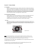
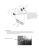
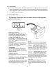
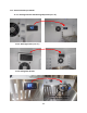
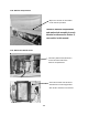
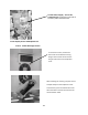
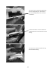
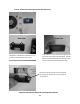
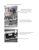
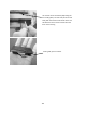
Table Of Contents
- Cover Page
- Section 0 (Table of Contents)
- Section 1 (Introduction)
- Section 2 (Sealed System)
- Section 3 (Sealed System Components)
- Section 4 (Electrical Component Access)
- Section 5 (User Interface Display)
- Section 6 (Control System)
- Section 7 (Lights, Doors, Drawer, and Hinges)
- Section 8 (Evaporator Compartment Access)
- Section 9 (Wiring Diagrams)
- Section 10 (Power On reset Mode)
- Section 11 (Quick Reference Troubleshooting)
- Section 12 (Diagnostic Flow Charts)
- Section 13 (Gathering Service Data)
- Section 14 (Beer Dispenser)
- Section 15 (Dual Zones)
- 15.1: User Interface Control
- 15.2: Operation
- 15.3: Characteristics
- 15.4: Dual Zone Compartment Air Flow
- 15.5: Divider Removal
- 15.6: Damper Operation
- 15.7: Compartment Fan Operation
- 15.8: Heater Operation
- 15.9: Thermistors
- 15.10: Evaporator Access
- 15.11: Interior LED’s
- 15.12: Defrost / Drip Time
- 15.13: Refrigeration and Mechanical
- Section 16 (Refrigerator Freezers)
- Section 17 (Outdoor Models)
- 17.1: Operation
- 17.2: Characteristics / Differences
- 17.3: Fans
- 17.4: Thermistors
- 17.5: Control Type
- 17.6 : Control Functions
- 17.7: Control Locations per Model
- 17.8: Machine Compartment
- 17.9: Main Power Board Access
- 17.10: Display Access and Replacement
- 17.11: Thermistor Resistance
- 17.12: Wiring Diagram
- 17.13: Generic Trouble shooting Charts
- 17.14: Refrigeration and Mechanical
- Section 18 (Prime Control)
- Section 19 (Clear Ice Machines)
- Section 20 (Service Kits / Bulletins)
- 20.1: Service Bulletin # 41013862Mullion Condensation on Refrigerated Drawers
- 20.2: SERVICE BULLETIN # 41013861EVAPORATOR REPLACEMENT KIT
- 20.3: SERVICE BULLETIN # 41013995 Rev CContact between the Door and Door Sensor
- 20.4: SERVICE BULLETIN # 41014167Slotted Condenser Shroud
- 20.5: SERVICE BULLETIN # 41014168Showroom Mode Alarm
- 20.6: SERVICE BULLETIN # 41014169Evaporator / Heat Exchanger Replacement(RF and RFI Models ONLY)
- 20.7: SERVICE BULLETIN # 41014241Shelf Shim Kit
- 20.8: Service Bulletin # 41014242Miscellaneous Control Communication Errors
- 20.9: Service Bulletin # 41014243Replacement of MP Door Skins
- Section 21 (Customer Service Contact Information)
- Section 22 (Notes)
- Back Page

156
Section 17: Outdoor Models
17.1: Operation
Dynamic cooling utilizing a forced air condenser and interior circulation fans moves air
effectively and efficiently. The Prime control system brings the control interface display
inboard where it will not be affected by the elements of the outdoors. The main control
board is located in the machine compartment. It is shielded by a mylar curtain behind
the compartment access cover, this also protects from the elements of the outdoors.
The entire cabinet and door are wrapped with a stainless finish.
17.2: Characteristics / Differences
Outdoor appliances are typically identified by the stainless steel wrapped cabinet and
matching stainless door. The control is located in the interior of the appliance.
In addition, the rear access panel in the machine compartment has a mylar curtain
installed along the top edge to prevent water or moisture from entering.
17.3: Fans
Fan function and location is not unlike the indoor Marvel and Marvel Pro models. Air is
drawn across the evaporator plate from the supply louvers and outward into the interior
cabinet through the circulation fan. The blades rotate in a clockwise direction as you
face the hub.
NOTE: As of mid-August 2015, a rear fan guard was added to the fan assemblies on the
outdoor beverage center and beverage dispenser models. The fan guard is to eliminate the
possibility of wires getting caught in the fan blade from behind the coil cover.
The approximate serial number range is 20150824xxxH. This is an approximate date and some
variation may be seen in the field.
An exploded view on the following page shows the assembly drawing of the coil cover
components along with both the front and rear fan guards.
Evaporator Fan