
Service Manual
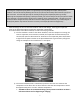
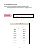
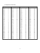
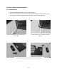

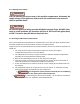
Table Of Contents
- Cover Page
- Section 0 (Table of Contents)
- Section 1 (Introduction)
- Section 2 (Sealed System)
- Section 3 (Sealed System Components)
- Section 4 (Electrical Component Access)
- Section 5 (User Interface Display)
- Section 6 (Control System)
- Section 7 (Lights, Doors, Drawer, and Hinges)
- Section 8 (Evaporator Compartment Access)
- Section 9 (Wiring Diagrams)
- Section 10 (Power On reset Mode)
- Section 11 (Quick Reference Troubleshooting)
- Section 12 (Diagnostic Flow Charts)
- Section 13 (Gathering Service Data)
- Section 14 (Beer Dispenser)
- Section 15 (Dual Zones)
- 15.1: User Interface Control
- 15.2: Operation
- 15.3: Characteristics
- 15.4: Dual Zone Compartment Air Flow
- 15.5: Divider Removal
- 15.6: Damper Operation
- 15.7: Compartment Fan Operation
- 15.8: Heater Operation
- 15.9: Thermistors
- 15.10: Evaporator Access
- 15.11: Interior LED’s
- 15.12: Defrost / Drip Time
- 15.13: Refrigeration and Mechanical
- Section 16 (Refrigerator Freezers)
- Section 17 (Outdoor Models)
- 17.1: Operation
- 17.2: Characteristics / Differences
- 17.3: Fans
- 17.4: Thermistors
- 17.5: Control Type
- 17.6 : Control Functions
- 17.7: Control Locations per Model
- 17.8: Machine Compartment
- 17.9: Main Power Board Access
- 17.10: Display Access and Replacement
- 17.11: Thermistor Resistance
- 17.12: Wiring Diagram
- 17.13: Generic Trouble shooting Charts
- 17.14: Refrigeration and Mechanical
- Section 18 (Prime Control)
- Section 19 (Clear Ice Machines)
- Section 20 (Service Kits / Bulletins)
- 20.1: Service Bulletin # 41013862Mullion Condensation on Refrigerated Drawers
- 20.2: SERVICE BULLETIN # 41013861EVAPORATOR REPLACEMENT KIT
- 20.3: SERVICE BULLETIN # 41013995 Rev CContact between the Door and Door Sensor
- 20.4: SERVICE BULLETIN # 41014167Slotted Condenser Shroud
- 20.5: SERVICE BULLETIN # 41014168Showroom Mode Alarm
- 20.6: SERVICE BULLETIN # 41014169Evaporator / Heat Exchanger Replacement(RF and RFI Models ONLY)
- 20.7: SERVICE BULLETIN # 41014241Shelf Shim Kit
- 20.8: Service Bulletin # 41014242Miscellaneous Control Communication Errors
- 20.9: Service Bulletin # 41014243Replacement of MP Door Skins
- Section 21 (Customer Service Contact Information)
- Section 22 (Notes)
- Back Page

9
Charge the unit to the specified amount (See unit specifications or serial plate
for charge specifications per model).
---------------------------------------------------------------------------------------------------------------------------
Listed below are two variations to correctly charge the sealed system
Method 1- DIAL-A-CHARGE
Method 2- Weigh in Liquid on High Side
DIAL-A-CHARGE Method
Using a length of manifold hose, connect one end to the manifold, the other end to the
weighted charging cylinder.
Adjust cylinder to weigh in the correct amount of refrigerant into system based on nameplate
charge.
It is best to use low loss fittings on hoses to avoid loss of charge when removing hoses.
Purge air from cylinder hose to manifold by loosening cylinder hose at manifold and bleeding
liquid through hose to manifold.
Open manifold and charge unit.
Run unit for at least 10 minutes to confirm that the unit has a full frost pattern on the
evaporator and that the unit is not overcharged and there is no liquid returning back to the
compressor.
It is normal to have some condensation or slight frost on the suction line. Typically this will
occur towards the end of a run cycle. If the frost continues down the suction line to the
compressor, the system is overcharged.
Once the system is charged, clamp off the process tube downstream from the access valve.
Remove the valve, cut off the extra process tube with the piercing, fill the open end of the
process tube with solder. Remove the clamp from the process tube and leak check.
Vacuum Pump Tips:
1) Remember to change vacuum pump oil after evacuating a
contaminated system.
2) Frequent oil changes will increase the pumps potential to
achieve the best vacuum possible.
3) Use recommended oil per recommendation of vacuum pump
manufacturer.