
Service Manual
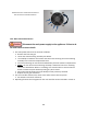
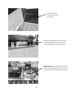
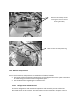
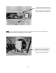
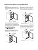

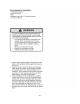
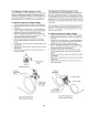
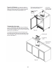
Table Of Contents
- Cover Page
- Section 0 (Table of Contents)
- Section 1 (Introduction)
- Section 2 (Sealed System)
- Section 3 (Sealed System Components)
- Section 4 (Electrical Component Access)
- Section 5 (User Interface Display)
- Section 6 (Control System)
- Section 7 (Lights, Doors, Drawer, and Hinges)
- Section 8 (Evaporator Compartment Access)
- Section 9 (Wiring Diagrams)
- Section 10 (Power On reset Mode)
- Section 11 (Quick Reference Troubleshooting)
- Section 12 (Diagnostic Flow Charts)
- Section 13 (Gathering Service Data)
- Section 14 (Beer Dispenser)
- Section 15 (Dual Zones)
- 15.1: User Interface Control
- 15.2: Operation
- 15.3: Characteristics
- 15.4: Dual Zone Compartment Air Flow
- 15.5: Divider Removal
- 15.6: Damper Operation
- 15.7: Compartment Fan Operation
- 15.8: Heater Operation
- 15.9: Thermistors
- 15.10: Evaporator Access
- 15.11: Interior LED’s
- 15.12: Defrost / Drip Time
- 15.13: Refrigeration and Mechanical
- Section 16 (Refrigerator Freezers)
- Section 17 (Outdoor Models)
- 17.1: Operation
- 17.2: Characteristics / Differences
- 17.3: Fans
- 17.4: Thermistors
- 17.5: Control Type
- 17.6 : Control Functions
- 17.7: Control Locations per Model
- 17.8: Machine Compartment
- 17.9: Main Power Board Access
- 17.10: Display Access and Replacement
- 17.11: Thermistor Resistance
- 17.12: Wiring Diagram
- 17.13: Generic Trouble shooting Charts
- 17.14: Refrigeration and Mechanical
- Section 18 (Prime Control)
- Section 19 (Clear Ice Machines)
- Section 20 (Service Kits / Bulletins)
- 20.1: Service Bulletin # 41013862Mullion Condensation on Refrigerated Drawers
- 20.2: SERVICE BULLETIN # 41013861EVAPORATOR REPLACEMENT KIT
- 20.3: SERVICE BULLETIN # 41013995 Rev CContact between the Door and Door Sensor
- 20.4: SERVICE BULLETIN # 41014167Slotted Condenser Shroud
- 20.5: SERVICE BULLETIN # 41014168Showroom Mode Alarm
- 20.6: SERVICE BULLETIN # 41014169Evaporator / Heat Exchanger Replacement(RF and RFI Models ONLY)
- 20.7: SERVICE BULLETIN # 41014241Shelf Shim Kit
- 20.8: Service Bulletin # 41014242Miscellaneous Control Communication Errors
- 20.9: Service Bulletin # 41014243Replacement of MP Door Skins
- Section 21 (Customer Service Contact Information)
- Section 22 (Notes)
- Back Page

106
14.2: Main Control Board Access
Caution Disconnect the main power supply to the appliance. Failure to do
so could result in severe shock.
1. The main power board can be accessed as follows:
Remove the front toe grill.
Locate the control housing assembly. See below.
Use a Phillips screwdriver and remove the two screws securing the control housing
assembly to the machine compartment base.
The control housing can now be slid outward away from the machine compartment.
NOTE: the rear of the control housing assembly is slotted to lock into a mounting
tab on the cabinet base. When re-installing; care must be taken to ensure that the
board is locked into place without pinching any wire harness.
Secure the control housing using the Phillips screws previously removed.
Replace the toe grill and secure.
2. The user interface functions the same as the other Aurora control systems.
See Sections 6 and 9 for reference.
3. Operating functions and navigation for the user interface can be reviewed in section 5.
Remove the four screws from the front of
the coil cover to remove either fan.