
Service Manual
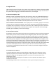
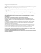
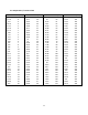
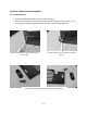

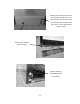
Table Of Contents
- Cover Page
- Section 0 (Table of Contents)
- Section 1 (Introduction)
- Section 2 (Sealed System)
- Section 3 (Sealed System Components)
- Section 4 (Electrical Component Access)
- Section 5 (User Interface Display)
- Section 6 (Control System)
- Section 7 (Lights, Doors, Drawer, and Hinges)
- Section 8 (Evaporator Compartment Access)
- Section 9 (Wiring Diagrams)
- Section 10 (Power On reset Mode)
- Section 11 (Quick Reference Troubleshooting)
- Section 12 (Diagnostic Flow Charts)
- Section 13 (Gathering Service Data)
- Section 14 (Beer Dispenser)
- Section 15 (Dual Zones)
- 15.1: User Interface Control
- 15.2: Operation
- 15.3: Characteristics
- 15.4: Dual Zone Compartment Air Flow
- 15.5: Divider Removal
- 15.6: Damper Operation
- 15.7: Compartment Fan Operation
- 15.8: Heater Operation
- 15.9: Thermistors
- 15.10: Evaporator Access
- 15.11: Interior LED’s
- 15.12: Defrost / Drip Time
- 15.13: Refrigeration and Mechanical
- Section 16 (Refrigerator Freezers)
- Section 17 (Outdoor Models)
- 17.1: Operation
- 17.2: Characteristics / Differences
- 17.3: Fans
- 17.4: Thermistors
- 17.5: Control Type
- 17.6 : Control Functions
- 17.7: Control Locations per Model
- 17.8: Machine Compartment
- 17.9: Main Power Board Access
- 17.10: Display Access and Replacement
- 17.11: Thermistor Resistance
- 17.12: Wiring Diagram
- 17.13: Generic Trouble shooting Charts
- 17.14: Refrigeration and Mechanical
- Section 18 (Prime Control)
- Section 19 (Clear Ice Machines)
- Section 20 (Service Kits / Bulletins)
- 20.1: Service Bulletin # 41013862Mullion Condensation on Refrigerated Drawers
- 20.2: SERVICE BULLETIN # 41013861EVAPORATOR REPLACEMENT KIT
- 20.3: SERVICE BULLETIN # 41013995 Rev CContact between the Door and Door Sensor
- 20.4: SERVICE BULLETIN # 41014167Slotted Condenser Shroud
- 20.5: SERVICE BULLETIN # 41014168Showroom Mode Alarm
- 20.6: SERVICE BULLETIN # 41014169Evaporator / Heat Exchanger Replacement(RF and RFI Models ONLY)
- 20.7: SERVICE BULLETIN # 41014241Shelf Shim Kit
- 20.8: Service Bulletin # 41014242Miscellaneous Control Communication Errors
- 20.9: Service Bulletin # 41014243Replacement of MP Door Skins
- Section 21 (Customer Service Contact Information)
- Section 22 (Notes)
- Back Page
6
2.3 High Side Leaks
High side leaks consist of a break in the system at the compressor, condenser, discharge tubing,
drier, or capillary tube. If a leak is found at any of these areas, replace or repair the leak. Flush
the system with nitrogen gas, evacuated to 50 microns, and recharged.
2.4 Restricted Capillary Tube
Moisture or other contaminants that enter the system can cause non condensable deposits in
the system. These deposits will usually collect in the capillary tube and form a restriction that
cannot be removed by flushing. If moisture is found in the system, the entire system has been
compromised due to the unstable relationship between ester oil and moisture.
For non-moisture related restrictions: If the capillary tube is restricted, typically the restriction
is at the inlet end, inserted into the drier. This can be repaired by cutting off approximately 1”
of capillary tube, inserting the cut end into a new drier, and re-soldering the joint. If the leak is
elsewhere in the capillary tube, it would be best to replace the evaporator / heat exchanger
assembly, pull a satisfactory vacuum and recharge.
2.5 Access/Process Valves
A temporary access valve can be used to service or evaluate the system. From these temporary
access valves, you can recover, evacuate, and re-charge the system. The access valve will be
installed on the compressor’s process tube (low pressure side). Be sure to cap off the access
valve if you have not completed servicing. This will prevent contamination of the system and
temporarily prevent refrigerant from leaking. After servicing is complete, the temporary valve
must be removed from the sealed system. A pinch-off tool can be used to close off the process
tube downstream from the valve piercing. Once this is done, the temporary valve can be
removed and the pierced section of the process tube cut off. The open end of the process tube
can now be soldered/brazed shut to seal the system. Be sure to leak check after brazing.
If a permanent soldered/brazed Schrader valve is used, the cap must be snugged firmly after
service is completed.
2.6 Evaporator Frost Pattern
In the past Marvel has always recommended not using a gauge set to determine system
capacity and pressures. The amount of refrigerant in these systems is so minute, that any
amount of charge lost during gauge installation or removal can be detrimental to the
refrigeration system.
It was determined that checking the frost pattern on the evaporator was always a good
indicator for reference.
The following procedure was recommended to check a typical cold plate evaporator: