
Use and Care Guide

NOTE
NOTE
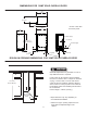
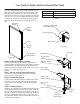
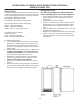
FULL OVERLAY PANEL INSTALLATION INSTRUCTIONS
Model W H
30iMT
14
5
⁄8"
(37.1cm)
30
5
⁄16"
(77.0cm)
30iMAT
14
5
⁄8"
(37.1cm)
27
11
⁄16"
(70.3cm)
For overlay with lock option
panel thickness to be
3
⁄4"
(19mm) maximum to
5
⁄8" (16mm) minimum.
Weight of the overlay panel
should not exceed 20 pounds
(9.1 kilograms).
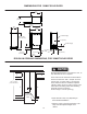
For the door to work properly it
is necessary to maintain a mini-
mum space of
9
⁄32" (7mm) between the door and cabinet
ange as shown . This space can be adjusted by adjusting
the top and bottom hinge adapters.
H
W
Figure 10
Table B
Front of
overlay
panel
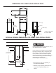
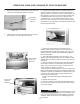
Step 5: Drill hinge clearance holes in overlay
panel
Set the overlay panel on the door front, align the edges,
and clamp together. Clamp the panel rmly but be careful
not to damage the door or the panel. Mark center of hinge
adapter hole on wood panel, top and bottom. (See Figure
11.) Remove wood panel from door and drill
5
⁄16" (8mm) di-
ameter clearance holes into the overlay panels
3
⁄4" (20mm)
deep. These will be clearance holes for the top and bottom
hinge pins.
This is also a convenient time to locate and drill the holes
for your handle. Most often the handle is to match that of
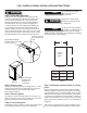
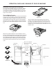
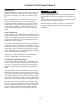
Step 1: Verify door alignment
Verify that the door is aligned correctly with the cabi-
net prior to fabricating the custom panel. Failure to do
so may result in mis-alignment of the custom panel
with the hinge bracket. The door should be parallel to
the sides and top of the ice machine. If alignment is
necessary the door may be adjusted by loosening the
2 screws which secure the top and/or bottom hinge
adapter brackets, located on the top and bottom of the
door and adjusting the door side to side. Use a
5
⁄32" allen
wrench, for this procedure. (See Figure 9 below). When
nished aligning the door, tighten the screws securely.
Remove top hinge
pin to remove the
door.
Door should be
parallel to top
and sides of
ice machine.
Step 2: Remove door
Remove the top hinge pin from the hinge with an
1
⁄8" allen
wrench. Remove the door by angling the top of the door
outward and lifting the door off the bottom hinge.
(See detail in Figure 9).
Step 3: Remove gasket
Lay the door on its front being careful not to scratch it. To
gain access to the screw mounting holes remove the door
gasket by peeling up and out of the channel.
Step 4: Cut overlay panel
Depending on the ice machine model cut the overlay panel
to the dimensions shown in Figure 10 and Table B.
Figure 9
Hinge adapter bracket
located on the top and bot-
tom of the door.
9
⁄32"
(7mm)
14