Installation Operation and Maintenance Instructions Clear Ice Models 3OiMT (Outdoor)
CONTENTS Important Safety Instructions.......................................... 3 Warranty Registration ................................................. 3 Installing your ice machine............................................. 4 Selecting the location................................................. 4 Outdoor Installation .................................................... 4 Cabinet Clearances ................................................... 4 Leveling legs ...........................................
IMPORTANT SAFETY INSTRUCTIONS Important Safety Instructions Warnings and safety instructions appearing in this guide are not meant to cover all possible conditions and situations that may occur. Common sense, caution, and care must be exercised when installing, maintaining, or operating this appliance. If the ice machine was shipped or has been laying on its back for any period of time allow the ice machine to sit upright for a period of at least 24 hours before plugging in.
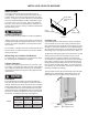
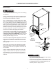
INSTALLING YOUR ICE MACHINE Select Location The proper location will ensure peak performance of your appliance. We recommend a location where the ice machine will be out of direct sunlight and away from heat sources. To assure your product performs to specifications the recommended installation location temperature range is from 55 to 80°F (13 to 27°C) for built in ice machines, 55 to 90°F (13 to 32°C) for freestanding ice machines.
INSTALLING THE DRAIN PLUMBING • • Risk of electrical shock or personal injury could occur due to moving components, if machine compartment access cover is removed before unplugging the ice machine. Do not splash or spray water from a hose on the ice machine. Doing so may cause an electrical shock, which may result in severe injury or death. This ice machine should not, under any circumstances, be installed to an un-grounded electrical supply. Drain Plumbing Your ice machine requires drain plumbing.
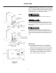
DRAIN PUMP The Marvel Drain Pump is designed to remove drain water from ice machines installed in areas without direct drainage access. The sealed reservoir pump collects the melted ice water and pumps it to a maximum lift of eight (8) feet (2.44 meters) through 3⁄8" I.D. vinyl tubing to a drain. Figure 5 This pump has been evaluated for use with water only. ⁄8" O.D. drain tubing and hose clamp 5 NOTE 1 ⁄2" Drain pipe 1 Reasonable care and safe methods should be practiced.
DRAIN PUMP Troubleshooting the Drain Pump NOTE If the drain pump reservoir (not the ice machine bin) reaches overfill condition, the power to the ice machine will be shut off. If the ice machine is not working, check the following: • Make sure there is power at the receptacle. • Make sure the ice machine is turned on. • Make sure the ice bin is not full. Then check the drain pump: The pump does not run: • Make sure the pump is plugged in and there is power to the receptacle.
CONNECTING THE WATER SUPPLY Water Supply Observe and follow all local building codes when installing this appliance. This ice machine must be connected to a potable cold water supply line. delivering water pressure between a minimum of 20 psi and a maximum of 120 psi. Use 1⁄4" copper tubing for your water supply which is available at any local hardware or plumbing supply store. Route the 1⁄4" copper tubing to suit your installation being sure not to kink the tubing.
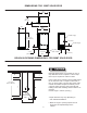
DIMENSIONS FOR 30IMT SOLID DOOR 211⁄2" (54.6cm) 169⁄16" (42.1cm) 371⁄16" (95.4cm) 251⁄2" (64.8cm) 14 ⁄8" (37.8cm) 7 CL water supply 333⁄4" to 343⁄4" (85.7 to 88.3cm) 11⁄8" (2.8cm) to water supply 53⁄32" (12.9cm) 3" to 4" (7.6 to 8.8cm) 2" (5.1cm) CL gravity drain 8" (20.3cm) 235⁄8" (60cm) ROUGH IN OPENING DIMENSIONS, FOR 30IMT SOLID DOOR Electrical Requirements: A grounded 115 volt, 15 amp dedicated circuit is required. A GFCI receptacle may be required for outdoor models.
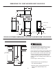
DIMENSIONS FOR 3OIMT AND MPRO30IMT SOLID DOOR 211⁄2" (54.6cm) 169⁄16" (42.1cm) 371⁄16" (95.4cm) 147⁄8" (37.8cm) 261⁄4" (66.7cm) CL water supply 333⁄4" to 343⁄4" (85.7 to 88.3cm) 11⁄8" (2.8cm) to water supply 53⁄32" (12.9cm) 3" to 4" (7.6 to 8.8cm) 2" (5.1cm) CL gravity drain 8" (20.3cm) 237⁄8" (60.6cm) ROUGH IN OPENING DIMENSIONS, FOR 3OIMT AND MPRO30IMT SOLID DOOR Electrical Requirements: A grounded 115 volt, 15 amp dedicated circuit is required.
DIMENSIONS FOR 30IMT SOLID OVERLAY DOOR 211⁄2" (54.6cm) 137⁄8" (35.3cm) 371⁄16" (95.4cm) * To face of door without custom panel 227⁄8"* (58.1cm) 14 ⁄8" (37.8cm) 7 CL water supply 11⁄8" (2.8cm) 333⁄4" to 343⁄4" (85.7 to 88.3cm) to water supply 53⁄32" (12.9cm) 3" to 4" (7.6 to 8.8cm) 2" (5.1cm) CL gravity drain 8" (20.3cm) ROUGH IN OPENING DIMENSIONS, FOR 30IMT SOLID OVERLAY DOOR Electrical Requirements: A grounded 115 volt, 15 amp dedicated circuit is required.
DIMENSIONS FOR 30IMAT SOLID DOOR 211⁄2" (54.6cm) 169⁄16" (42.1cm) 371⁄16" (95.4cm) 147⁄8" (37.8cm) 251⁄2" (64.8cm) CL water supply 311⁄8" to 321⁄8" (79.1 to 81.6cm) 11⁄8" (2.8cm) to water supply 53⁄32" (12.9cm) 3" to 4" (7.6 to 8.8cm) CL gravity drain 2" (5.1cm) 8" (20.3cm) 235⁄8" (60cm) ROUGH IN OPENING DIMENSIONS, FOR 30IMAT SOLID DOOR Electrical Requirements: A grounded 115 volt, 15 amp dedicated circuit is required. Power outlet can be located in the back wall behind the ice machine.
DIMENSIONS FOR 30IMAT SOLID OVERLAY DOOR 211⁄2" (54.6cm) 137⁄8" (35.3cm) 371⁄16" (95.4cm) 227⁄8"* (58.1cm) 147⁄8" (37.8cm) CL water supply 11⁄8" (2.8cm) 311⁄8" to 321⁄8" (79.1 to 81.6cm) to water supply 53⁄32" (12.9cm) 3" to 4" (7.6 to 8.8cm) 2" (5.1cm) CL gravity drain * To face of door without custom panel 8" (20.3cm) ROUGH IN OPENING DIMENSIONS, FOR 30IMAT SOLID OVERLAY DOOR Electrical Requirements: A grounded 115 volt, 15 amp dedicated circuit is required.
FULL OVERLAY PANEL INSTALLATION INSTRUCTIONS For overlay with lock option panel thickness to be 3⁄4" 5 (19mm) maximum to ⁄8" (16mm) minimum. NOTE Step 1: Verify door alignment Verify that the door is aligned correctly with the cabinet prior to fabricating the custom panel. Failure to do so may result in mis-alignment of the custom panel with the hinge bracket. The door should be parallel to the sides and top of the ice machine.
FULL OVERLAY PANEL INSTALLATION INSTRUCTIONS the surrounding cabinetry. If your handle attaches from the back-side of the custom panel, locate the mounting holes while the panel is attached to the door and cabinet. After the panel is removed from the door, drill the mounting holes from the front, to the recommended diameter of the handle manufacturer. Counter bore the back-side of the panel so the screw heads do not interfere with the surface of the door.
OPERATION, CARE, AND CLEANING OF YOUR ICE MACHINE Operation (Turning on the ice machine) Once the drain and water supply are connected, and the ice machine is in place and leveled, plug in the service cord. Place the switch to the "ON" position to turn on the ice machine. The switch is located in the front grille, see Figure 15 for location.
OPERATION, CARE, AND CLEANING OF YOUR ICE MACHINE Care of the Ice Machine The bin level sensor is located in the ice bin, it senses when the ice supply is low or full and starts or stops the ice making process accordingly. If the water supply is turned off to the ice machine be sure to set the selector switch to the "OFF" position. 1. Avoid leaning on the cabinet door. You may bend the door hinge or tip the ice machine. 2.
OPERATION, CARE, AND CLEANING OF YOUR ICE MACHINE 4. 6. Determine the proper amount of cleaner from the ice machine cleaner manufacturer’s mixture ratio based on 3⁄4 gallon (2.81 liters) of water (refer to the manufacturer’s mix ratio directions). Check to be sure the reservoir drain plug is installed that was removed in step 4. Add the recommended amount of concentrated cleaning solution to the reservoir of the ice machine.
STAINLESS STEEL MAINTENANCE Background Stainless steel does not stain, corrode, or rust as easily as ordinary steel, but it is not stain or corrosion proof. Stainless steels can discolor or corrode if not maintained properly. Stainless steels differ from ordinary carbon steels by the amount of chromium present. It is this chromium that provides an invisible protective film on the surface called chrome-oxide.
FILLER PANEL KIT INSTALLATION INSTRUCTIONS (OPTIONAL) ENERGY SAVING TIPS Filler Panel Kit This Filler Panel Kit will add 3 inches to the width of the ice machine for installation into an 18 inch wide opening.
TROUBLESHOOTING GUIDE cycles can take longer. Check the ice machine after 24 hours for ice accumulation in the bin. Is the reservoir drain plug in place? Check that the reservoir drain plug is properly seated. Before calling a service provider try the trouble shooting suggestions below. Ice Machine Operation Ice machine does not operate Is the ice machine’s power cord plugged in? Plug the power cord into a grounded 3 prong outlet.
TROUBLESHOOTING GUIDE PREPARING THE ICE MACHINE FOR STORAGE Is the distributor tube restricted? Check the water line to the ice machine to make sure there are no restrictions or kinks in the line. Check all filters to make sure they are not restricted. Check that the water flows evenly out of the distributor tube, if not, clean the ice machine. See "Cleaning the Ice Machine".
PREPARING THE ICE MACHINE FOR STORAGE Figure 24 Back view of ice machine Water supply line Figure 26 Water supply fitting To disconnect the water outlet line: Push up on the white collar and pull the plastic water line from the bottom of the water valve. Water valve inlet Figure 24a To reconnect the water outlet line: Simply insert the plastic tubing into the white collar and push until it stops (about 1⁄2", 12 mm, of water line will enter the valve).
DRAIN PUMP REMOVAL INSTRUCTIONS Drain Pump Removal Instructions: Drain valve 1. Unplug ice machine from the electrical supply and remove the rear access cover from the ice machine. (See page 6 for instructions). 2. Unscrew the leveling leg in the back corner until the end of the threaded portion is flush with the threaded nut insert in the base. (see Figure 28 ). 3. Unscrew the 4 hose clamps and remove the 3 hoses from the front of the drain pump. (See Figure 28). 4.
DRAIN PUMP REMOVAL INSTRUCTIONS Additional issues to be inspected by the installer upon service replacement: 1. 2. 3. 4. 5. 6. 7. 8. 9. 10. 11. 12. The drain pump must be level. No pinched water lines. No interference with electrical cords or wiring. The drain pump should not set on any obstacles, wiring, etc. Secure all hose clamps leading to and from the drain pump. Insure that the vent tube height is adequate - 18 inch minimum. Insure that drain height is adequate - maximum of 8 foot.
OBTAINING SERVICE Before Calling for Service How to Obtain Service Before calling for service, check the following items: • • • • • • • Your ice machine requires little service because the best and most up to date materials, equipment and quality methods are employed throughout the manufacturing process. Make sure the ice machine is plugged into an outlet. Check the outlet for power. Test outlet with lamp to make certain outlet has power. Make sure ice machine’s switch is in the "ON" position.
HOUSEHOLD PRODUCT WARRANTY Entire Product Limited One Year Parts and Labor Warranty Parts or Service Not Supplied or Designated by AGA MARVEL AGA MARVEL warrants that it will supply all necessary parts and labor to repair or replace in the end user’s home or office, any component which proves to be defective in material or workmanship, subject to the condition and exclusions stated below, for a period of one year from the date of purchase by the end user.
www.agamarvel.com 1260 E. VanDeinse St. Greenville MI 48838 800.223.3900 41012687-EN rev H 3/23/18 All specifications and product designs subject to change without notice. Such revisions do not entitle the buyer to corresponding changes, improvements, additions, replacements or compensation for previously purchased products.
Instructions d’installation, d’utilisation et d’entretien Machine à glaçons "Clear Ice" 3OiMT (Extérieur)
CONTENU Déballage de votre machine à glaçons................ .......... 3 Enlèvement de l’emballage..................................... ... 3 Enregistrement de la garantie..................................... 3 Installation de votre machine à glaçons......................... 4 Choix de l’emplacement à l’extérieur........................... 4 Préparation pour l’hiver............................................... 4 Écartements pour l’armoire......................................... 4 Pieds de mise à niveau.
DÉBALLAGE DE VOTRE MACHINE À GLAÇONS Importantes instructions de sécurité ATTENTION Les avertissements et les instructions de sécurité qui apparaissent dans ce guide n’ont pas la prétention de couvrir toutes les conditions et situations possibles pouvant arriver. Il faut faire preuve de bon sens, de précautions et de soins, pour installer, utiliser ou entretenir cet appareil.
INSTALLATION DE VOTRE MACHINE À GLAÇONS Grille de plinthe frontale, gardez cette zone dégagée. Choix de l’emplacement Un bon emplacement assurera une performance de pointe pour votre appareil. Nous recommandons un endroit où l’appareil ne sera pas exposé directement au rayonnement solaire et restera écartée de sources de chauffage.
INSTALLATION DE LA PLOMBERIE DE DRAINAGE ATTENTION • • AVERTISSEMENT Un risque de commotion électrique ou de blessure corporelle peut venir de composants en mouvement si le couvercle d’accès au compartiment de la machine est enlevé avant d’avoir débranché électriquement la machine à glaçons. N’envoyez pas d’eau par éclaboussure ou par jet d’un tuyau sur la machine à glaçons. Cela pourrait causer une commotion électrique, entraînant potentiellement des blessures graves voire mortelles.
POMPE DE DRAINAGE La pompe de drainage Marvel est conçue pour éliminer l’eau de drainage des machines à glaçons dans les lieux où existe un accès direct au drain. La pompe à réservoir scelle collecte l’eau de glace fondue, et la propulse avec une élévation maximale de 8 pieds (2,4 m) au travers d’un tube vinyle de diamètre interne de 3⁄8 de pouce vers un drain. Figure 5 ATTENTION Cette pompe a été évaluée pour être utilisée avec de l’eau uniquement. Tube de drainage Ø ext.
POMPE DE DRAINAGE Dépannage (pompe de drainage installée sur le site) AVIS : Si le réservoir de la pompe de drainage (et non le bac de la machine à glaçons) arrive à un état de débordement, il faut couper l’alimentation de la machine à glaçons. Si la machine à glaçons ne fonctionne pas, vérifiez ce qui suit : • Assurez-vous que la tension secteur est bien présente sur la prise. • Assurez-vous que la machine à glaçons est bien mise en marche. • Assurez-vous que le bac à glaçons n’est pas déjà plein.
BRANCHEMENT DE L’ARRIVÉE D’EAU Alimentation en eau ATTENTION Respectez et observez toutes les normes locales pour l’installation de cet appareil. Utilisez du tube de cuivre de 1⁄4” pour votre arrivée d’eau, disponible localement dans toute quincaillerie ou magasin de fournitures de plomberie. Formez le tuyau de cuivre de 1⁄4” en fonction des besoins de votre installation, en prenant soin de ne pas le pincer.
DIMENSIONS POUR PORTE PLEINE DE 30IMT 211⁄2 po (54,6 cm) 169⁄16 po (42,1 cm) 371⁄16 po (95,4 cm) 147⁄8 po (37,8 cm) 251⁄2 po (64,7 cm) Alim. en eau (conduite cuivre) 333⁄4 po á 343⁄4 po (85,7 á 88,3 cm) 11⁄8 po (2,8cm) Alim.
DIMENSIONS POUR PORTE PLEINE DE 3OIMT AND MPRO30IMT 211⁄2 po (54,6 cm) 169⁄16 po (42,1 cm) 371⁄16 po (95,4 cm) 147⁄8 po (37,8 cm) 261⁄4 po (66,7 cm) Alim. en eau (conduite cuivre) 333⁄4 po á 343⁄4 po (85,7 á 88,3 cm) 11⁄8 po (2,8cm) Alim.
DIMENSIONS DE PORTE À REVÊTEMENT PLEIN DE 30IMT 211⁄2 po (54,6 cm) 137⁄8 po (35,3 cm) 371⁄16 po (95,4 cm) * Pour recouvrir une porte sans panneau personnalisé 227⁄8 po* (58,1 cm) 14 ⁄8 po (37,8cm) 7 Alim. en eau (conduite cuivre) 11⁄8 po (2,8cm) 333⁄4 po á 343⁄4 po (85,7 á 88,3 cm) Alim.
DIMENSIONS DE PORTE PLEINE POUR 30IMAT 211⁄2 po (54,6 cm) 169⁄16 po (42,1 cm) 371⁄16 po (95,4 cm) 147⁄8 po (37,8 cm) 251⁄2 po (64,8 cm) Alim. en eau (conduite cuivre) 311⁄8 po á 321⁄8 po (79,1 á 81,6 cm) 11⁄8 po (2,8cm) Alim.
DIMENSIONS DE PORTE À REVÊTEMENT PLEIN DE 30IMAT 211⁄2 po (54,6 cm) 137⁄8 po (35,3 cm) 371⁄16 po (95,4 cm) 227⁄8 po* (58,1 cm) 147⁄8 po (37,8 cm) Alim. en eau (conduite cuivre) 311⁄8 po á 321⁄8 po (79,1 á 81,6 cm) 11⁄8 po (2,8cm) Alim.
INSTRUCTIONS D’INSTALLATION DE PANNEAU DE REVÊTEMENT COMPLET REMARQUE NOTE ATTENTION Pour un revêtement avec option de verrouillage, l’épaisseur de panneau doit faire 3⁄4 po (19 mm) au maximum et 5⁄8 po (16 mm) au minimum. Étape 1 : Vérification de l’alignement de porte Vérifiez que la porte est correctement alignée par rapport à l’armoire avant de fabriquer le panneau sur mesures. Sinon cela peut amener un désalignement du panneau sur mesures avec le support de charnière.
INSTRUCTIONS D’INSTALLATION DE PANNEAU DE REVÊTEMENT COMPLET Une fois le panneau retiré de la porte, percez les trous de montage depuis la face avant, au diamètre recommandé par le fabricant de poignée. Fraisez sur la face arrière du panneau de façon à ce que les têtes de vis n’interfèrent pas avec la surface de la porte.
FONCTIONNEMENT, ENTRETIEN ET NETTOYAGE DE VOTRE MACHINE À GLAÇONS Utilisation (Mise en marche de la machine à glaçons) Une fois que les liaisons de drainage et d’alimentation en eau sont réalisées, et que la machine à glaçons est en place et mise de niveau, branchez son cordon d’alimentation. Passez ce commutateur en position de marche (ON) pour démarrer la machine à glaçons. L’interrupteur est placé sur la grille frontale, consultez la Figure 15 pour situer cet emplacement.
FONCTIONNEMENT, ENTRETIEN ET NETTOYAGE DE VOTRE MACHINE À GLAÇONS Entretien de la machine à glaçons Le capteur de niveau de glaçons est situé dans le bac, il détecte quand la fourniture de glaçons est faible et lance ou arrête la fabrication de glaçons en conséquence. 1. 2. REMARQUE NOTE 3. Si l’arrivée d’eau à la machine à glaçon est coupée, placez la commande sur " OFF " 4.
FONCTIONNEMENT, ENTRETIEN ET NETTOYAGE DE VOTRE MACHINE À GLAÇONS 4. Enlevez le bouchon de vidange au fond du réservoir pour éliminer tout ce qui reste d’eau, puis remettez-le en place. 6. Bouchon de vidange au fond du réservoir Déterminez la bonne quantité de produit nettoyant en fonction des instructions de son fabricant pour un mélange adéquat sur la base de 3/4 de gallon (2,81 litres) (reportezvous aux instructions de mé lange du fabricant).
ENTRETIEN DE L’ACIER INOX Contexte L’acier inox ne se décolore pas, ne se corrode pas et ne rouille pas comme l’acier ordinaire, mais il n’est pas à l’abri des taches ou corrosions. L’acier inox peut se décolorer ou se corroder s’il n’est pas entretenu correctement. REMARQUE NOTE Quelque soit votre choix du produit de nettoyage, il doit être utilisé en conformité stricte avec les instructions de son fabricant.
INSTRUCTIONS D’INSTALLATION DU KIT DE PANNEAUX DE REMPLISSAGE (OPTIONNEL) Ce kit de panneaux de remplissage ajoutera 3 pouces (7,5 cm) à la machine à glaçons pour son installation dans une niche de 18 pouces de large.
GUIDE DE DÉPANNAGE Avant d’appeler un prestataire de service, essayez les suggestions de dépannage suivantes. Le bouchon de drainage du réservoir est-il en place ? Vérifiez que ce bouchon de drainage de réservoir est bien fermé. Fonctionnement de la machine à glaçons Le tube de distributeur d’eau est-il restreint ? Lancez un cycle de nettoyage pour nettoyer la machine à glaçons. Contrôlez également qu’aucun des filtres n’est obstrué.
GUIDE DE DÉPANNAGE PRÉPARATION À L’ENTREPOSAGE DE LA MACHINE À GLAÇONS Nettoyage de la machine à glaçons Problèmes de plomberie Le nettoyage de la machine à glaçons aidera à éviter la croissance de moisissures et assainira également l’appareil en prévision d’un entreposage ou au moment de sa remise en service. Reportez-vous à la page 17 pour le nettoyage de la machine à glaçons.
PRÉPARATION À L’ENTREPOSAGE DE LA MACHINE À GLAÇONS Figure 24 Vue arrière de la machine à glaçons Conduite d'alimentation en eau Figure 26 Raccord de l'alimentation en eau Entrée du robinet d'eau Pour débrancher la conduite Figure 24a de la sortie d'eau : Poussez sur le collet blanc vers le haut et tirez sur la conduite de la sortie d'eau à partir du bas du robinet d'eau.
INSTRUCTIONS DE DÉMONTAGE DE POMPE DE DRAINAGE Instructions pour déposer la pompe de drainage : 1. 2. 3. 4. 5. 6. Vanne de drainage Débranchez l’alimentation électrique de la machine à glaçons et ôtez son couvercle d’accès à l’arrière (Voir la page 6 pour les instructions).
INSTRUCTIONS DE DÉMONTAGE DE POMPE DE DRAINAGE Points supplémentaires à inspecter par l’installateur pour un remplacement : Cordon d’alimentation à glaçons 1) La pompe de drainage doit être de niveau. 2) Les conduites d’eau ne doivent pas être pincées. 3) Il ne doit pas y avoir d’interférence avec des cordons électriques ou le câblage. 4) La pompe de drainage ne doit pas être placée sur des obstacles quelconques, du câblage, etc.
OBTENTION DU SERVICE Avant d’appeler pour du service Comment obtenir le service Avant d’appeler pour demander du service, vérifiez les points suivants : • • • • • • • Votre machine à glaçons nécessite peu de service, car c’est le meilleur et le dernier cri en matériaux, équipements et méthodes de qualité qui a été employé tout au long de son processus de construction. Assurez-vous que la machine est bien branchée sur la prise secteur. Vérifiez la présence du secteur sur cette prise.
GARANTIE D’APPAREIL À USAGE DOMESTIQUE Appareil complet Garantie limitée d’un an sur pièces et maind’œuvre Pièces ou service non fournis ou conçus par AGA MARVEL Les garanties qui précèdent ne s’appliquent pas non plus si : AGA MARVEL garantit qu’il fournira toutes les pièces et la maind’œuvre nécessaires pour réparer ou remplacer, au domicile ou au bureau de l’utilisateur final, tout composant avéré défectueux du fait des matériaux ou de la main-d’œuvre, en tenant compte des conditions et exclusions décr
www.agamarvel.com 1260 E. VanDeinse St. Greenville MI 48838 800.223.3900 41012687-CFR rev H 3/23/18 Toutes les spécifications et les conceptions des produits sont sujettes à des changements sans préavis. De telles révisions ne donnent aucun droit pour l’acheteur de produits antérieurs à bénéficier de ces changements, améliorations, ajouts, remplacements, ni de recevoir une compensation.