Installation Operation and Maintenance Instructions Clear Ice Models 3OiMT (Outdoor)
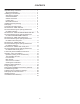
CONTENTS Important Safety Instructions.......................................... 3 Warranty Registration ................................................. 3 Installing your ice machine............................................. 4 Selecting the location................................................. 4 Outdoor Installation .................................................... 4 Cabinet Clearances ................................................... 4 Leveling legs ...........................................
IMPORTANT SAFETY INSTRUCTIONS Important Safety Instructions Warnings and safety instructions appearing in this guide are not meant to cover all possible conditions and situations that may occur. Common sense, caution, and care must be exercised when installing, maintaining, or operating this appliance. If the ice machine was shipped or has been laying on its back for any period of time allow the ice machine to sit upright for a period of at least 24 hours before plugging in.
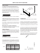
INSTALLING YOUR ICE MACHINE Select Location The proper location will ensure peak performance of your appliance. We recommend a location where the ice machine will be out of direct sunlight and away from heat Front Grille, keep this area open. the recommended installation location temperature range is from 55 to 80°F (13 to 27°C) for built in ice machines, 55 to 90°F (13 to 32°C) for freestanding ice machines. Ice machine will not perform correctly in ambient temperatures less than 55°F (13°C).
INSTALLING THE DRAIN PLUMBING • • Risk of electrical shock or personal injury could occur due to moving components, if machine compartment access cover is removed before unplugging the ice machine. Do not splash or spray water from a hose on the ice machine. Doing so may cause an electrical shock, which may result in severe injury or death. This ice machine should not, under any circumstances, be installed to an un-grounded electrical supply. Drain Plumbing Your ice machine requires drain plumbing.
DRAIN PUMP The Marvel Drain Pump is designed to remove drain water from ice machines installed in areas without direct drainage access. The sealed reservoir pump collects the melted ice water and pumps it to a maximum lift of eight (8) feet (2.44 meters) through 3 8" I.D. vinyl tubing to a drain. Figure 5 This pump has been evaluated for use with water only. " O.D. drain tubing and hose clamp 5 8 11 2" Drain pipe Reasonable care and safe methods should be practiced.
DRAIN PUMP Troubleshooting the Drain Pump If the drain pump reservoir (not the ice machine bin) be shut off. If the ice machine is not working, check the following: • Make sure there is power at the receptacle. • Make sure the ice machine is turned on. • Make sure the ice bin is not full. Then check the drain pump: The pump does not run: • Make sure the pump is plugged in and there is power to the receptacle. • Check the inlet to the drain pump for debris and clean as needed.
CONNECTING THE WATER SUPPLY Water Supply Observe and follow all local building codes when installing this appliance. This ice machine must be connected to a potable cold water supply line. delivering water pressure between a minimum of 20 psi and a maximum of 120 psi. Use 1 4" copper tubing for your water supply which is available at any local hardware or plumbing supply store. Route the 1 4" copper tubing to suit your installation being sure not to kink the tubing.
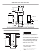
DIMENSIONS FOR 30IMT SOLID DOOR 211 2" (54.6cm) 169 16" (42.1cm) 371 16" (95.4cm) 251 2" (64.8cm) 14 8" (37.8cm) 7 CL water supply 333 4" to 343 4" (85.7 to 88.3cm) 11 8" (2.8cm) to water supply 53 32" (12.9cm) 3" to 4" (7.6 to 8.8cm) 2" (5.1cm) CL gravity drain 8" (20.3cm) 235 8" (60cm) ROUGH IN OPENING DIMENSIONS, FOR 30IMT SOLID DOOR Electrical Requirements: A grounded 115 volt, 15 amp dedicated circuit is required. A GFCI receptacle may be required for outdoor models.
DIMENSIONS FOR 3OIMT AND MPRO30IMT SOLID DOOR 211 2" (54.6cm) 169 16" (42.1cm) 371 16" (95.4cm) 147 8" (37.8cm) 261 4" (66.7cm) CL water supply 333 4" to 343 4" (85.7 to 88.3cm) 11 8" (2.8cm) to water supply 53 32" (12.9cm) 3" to 4" (7.6 to 8.8cm) 2" (5.1cm) CL gravity drain 8" (20.3cm) 237 8" (60.6cm) ROUGH IN OPENING DIMENSIONS, FOR 3OIMT AND MPRO30IMT SOLID DOOR Electrical Requirements: A grounded 115 volt, 15 amp dedicated circuit is required.
DIMENSIONS FOR 30IMT SOLID OVERLAY DOOR 211 2" (54.6cm) 137 8" (35.3cm) 371 16" (95.4cm) * To face of door without custom panel 227 8"* (58.1cm) 14 8" (37.8cm) 7 CL water supply 11 8" (2.8cm) 333 4" to 343 4" (85.7 to 88.3cm) to water supply 53 32" (12.9cm) 3" to 4" (7.6 to 8.8cm) 2" (5.1cm) CL gravity drain 8" (20.3cm) ROUGH IN OPENING DIMENSIONS, FOR 30IMT SOLID OVERLAY DOOR Electrical Requirements: A grounded 115 volt, 15 amp dedicated circuit is required.
DIMENSIONS FOR 30IMAT SOLID DOOR 211 2" (54.6cm) 169 16" (42.1cm) 371 16" (95.4cm) 147 8" (37.8cm) 251 2" (64.8cm) CL water supply 311 8" to 321 8" (79.1 to 81.6cm) 11 8" (2.8cm) to water supply 53 32" (12.9cm) 3" to 4" (7.6 to 8.8cm) CL gravity drain 2" (5.1cm) 8" (20.3cm) 235 8" (60cm) ROUGH IN OPENING DIMENSIONS, FOR 30IMAT SOLID DOOR Electrical Requirements: A grounded 115 volt, 15 amp dedicated circuit is required. Power outlet can be located in the back wall behind the ice machine.
DIMENSIONS FOR 30IMAT SOLID OVERLAY DOOR 211 2" (54.6cm) 137 8" (35.3cm) 371 16" (95.4cm) 227 8"* (58.1cm) 147 8" (37.8cm) CL water supply 11 8" (2.8cm) 311 8" to 321 8" (79.1 to 81.6cm) to water supply 53 32" (12.9cm) 3" to 4" (7.6 to 8.8cm) 2" (5.1cm) CL gravity drain * To face of door without custom panel 8" (20.3cm) ROUGH IN OPENING DIMENSIONS, FOR 30IMAT SOLID OVERLAY DOOR Electrical Requirements: A grounded 115 volt, 15 amp dedicated circuit is required.
FULL OVERLAY PANEL INSTALLATION INSTRUCTIONS For overlay with lock option panel thickness to be 3 4" 5 (19mm) maximum to 8" (16mm) minimum. Step 1: Verify door alignment Verify that the door is aligned correctly with the cabinet prior to fabricating the custom panel. Failure to do so may result in mis-alignment of the custom panel with the hinge bracket. The door should be parallel to the sides and top of the ice machine.
FULL OVERLAY PANEL INSTALLATION INSTRUCTIONS the surrounding cabinetry. If your handle attaches from the back-side of the custom panel, locate the mounting holes while the panel is attached to the door and cabinet. After the panel is removed from the door, drill the mounting holes from the front, to the recommended diameter of the handle manufacturer. Counter bore the back-side of the panel so the screw heads do not interfere with the surface of the door.
OPERATION, CARE, AND CLEANING OF YOUR ICE MACHINE Operation (Turning on the ice machine) Once the drain and water supply are connected, and the ice machine is in place and leveled, plug in the service cord. Place the switch to the "ON" position to turn on the ice machine. The switch is located in the front grille, see Figure 15 for location.
OPERATION, CARE, AND CLEANING OF YOUR ICE MACHINE Care of the Ice Machine The bin level sensor is located in the ice bin, it senses when the ice supply is low or full and starts or stops the ice making process accordingly. If the water supply is turned off to the ice machine be sure to set the selector switch to the "OFF" position. 1. Avoid leaning on the cabinet door. You may bend the door hinge or tip the ice machine. 2.
OPERATION, CARE, AND CLEANING OF YOUR ICE MACHINE 4. 6. Determine the proper amount of cleaner from the ice machine cleaner manufacturer’s mixture ratio based on 3 4 gallon (2.81 liters) of water (refer to the manufacturer’s mix ratio directions). Check to be sure the reservoir drain plug is installed that was removed in step 4. Add the recommended amount of concentrated cleaning solution to the reservoir of the ice machine.
STAINLESS STEEL MAINTENANCE Background Stainless steel does not stain, corrode, or rust as easily as ordinary steel, but it is not stain or corrosion proof. Stainless steels can discolor or corrode if not maintained properly. Stainless steels differ from ordinary carbon steels by the amount of chromium present. It is this chromium that surface can be damaged or contaminated, which may result in discoloration, staining, or corrosion of the base metal.
FILLER PANEL KIT INSTALLATION INSTRUCTIONS (OPTIONAL) ENERGY SAVING TIPS Filler Panel Kit This Filler Panel Kit will add 3 inches to the width of the ice machine for installation into an 18 inch wide opening.
TROUBLESHOOTING GUIDE cycles can take longer. Check the ice machine after 24 hours for ice accumulation in the bin. Is the reservoir drain plug in place? Check that the reservoir drain plug is properly seated. Before calling a service provider try the trouble shooting suggestions below. Ice Machine Operation Is the water distributor tube restricted? Run a cleaning Is the ice machine’s power cord plugged in? Plug the power cord into a grounded 3 prong outlet. make sure they are not restricted.
TROUBLESHOOTING GUIDE PREPARING THE ICE MACHINE FOR STORAGE Is the distributor tube restricted? Check the water line to the ice machine to make sure there are no restrictions or Risk of electrical shock or personal injury could occur due to moving components, if machine compartment access cover is removed before unplugging the ice machine. distributor tube, if not, clean the ice machine. See "Cleaning the Ice Machine".
PREPARING THE ICE MACHINE FOR STORAGE Figure 24 Back view of ice machine Water supply line Figure 26 Water supply To disconnect the water outlet line: Push up on the white collar and pull the plastic water line from the bottom of the water valve. Water valve inlet Figure 24a To reconnect the water outlet line: Simply insert the plastic tubing into the white collar and push until it stops (about 1 2", 12 mm, of water line will enter the valve).
DRAIN PUMP REMOVAL INSTRUCTIONS Drain Pump Removal Instructions: Drain valve 1. Unplug ice machine from the electrical supply and remove the rear access cover from the ice machine. (See page 6 for instructions). 2. Unscrew the leveling leg in the back corner until the nut insert in the base. (see Figure 28 ). 3. Unscrew the 4 hose clamps and remove the 3 hoses from the front of the drain pump. (See Figure 28). 4. Rotate the drain pump and remove from the ice machine, (See Figure 27).
DRAIN PUMP REMOVAL INSTRUCTIONS Additional issues to be inspected by the installer upon service replacement: 1. 2. 3. 4. 5. 6. 7. 8. 9. 10. 11. 12. The drain pump must be level. No pinched water lines. No interference with electrical cords or wiring. The drain pump should not set on any obstacles, wiring, etc. Secure all hose clamps leading to and from the drain pump. Insure that the vent tube height is adequate - 18 inch minimum. Insure that drain height is adequate - maximum of 8 foot.
OBTAINING SERVICE Before Calling for Service How to Obtain Service Before calling for service, check the following items: • • • • • • • Your ice machine requires little service because the best and most up to date materials, equipment and quality methods are employed throughout the manufacturing process. Make sure the ice machine is plugged into an outlet. Check the outlet for power. Test outlet with lamp to make certain outlet has power. Make sure ice machine’s switch is in the "ON" position.
HOUSEHOLD PRODUCT WARRANTY Entire Product Limited One Year Parts and Labor Warranty Parts or Service Not Supplied or Designated by AGA MARVEL AGA MARVEL warrants that it will supply all necessary parts and labor to repair or replace in the end user’s home The above warranties also do not apply if: in material or workmanship, subject to the condition and exclusions stated below, for a period of one year from the date of purchase by the end user.
www.agamarvel.com 1260 E. VanDeinse St. Greenville MI 48838 800.223.3900 41012687-EN rev H 3/23/18 entitle the buyer to corresponding changes, improvements, additions, replacements or compensation for previously purchased products.
O N O F F C L E A N O N O N O F F C L E A N O F F