
User guide


8 MAC Viper Profile Safety and Installation Guide
Physical installation
Warning! The MAC Viper Profile has a powerful pan motor. The torque reaction when the head is
panned suddenly can cause the base to move if the fixture is standing unsecured on a surface. Do
not apply power to the MAC Viper Profile unless the base is securely fastened to a surface or to
rigging hardware.
Warning! Use 2 clamps to rig the fixture. Do not hang the fixture from only one clamp. Lock each
clamp with both 1/4-turn fasteners. Fasteners are locked only when turned fully clockwise.
Warning! When suspending the fixture above ground level, secure it against failure of primary
attachments by attaching a safety wire that is approved as a safety attachment for the weight of the
fixture to the attachment point in the base. Do not use the carrying handles for secondary
attachment.
Warning! When clamping the fixture to a truss or other structure at any other angle than with the
yoke hanging vertically downwards, use two clamps of half-coupler type. Do not use any type of
clamp that does not completely encircle the structure when fastened.
Warning! Position or shade the head so that the lens does not face the sun at any time – even for a
few seconds – during daylight hours. The MAC Viper Profile’s lens can focus the sun's rays inside
the fixture, creating a potential fire hazard and causing internal damage.
Important! Do not point the output from other lighting fixtures at the MAC Viper Profile from a
distance of less than 3 m (10 ft.), as intense illumination can damage the display.
The MAC Viper Profile
can be fastened to a
surface such as a stage
or clamped to a truss in
any orientation. Clamps
must be half-coupler type
(see Figure 3) unless the
fixture is installed with
the yoke hanging
vertically downwards, in
which case other clamp
types that are approved
for the supported weight
may be used.
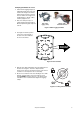
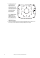
The mounting points
allow the clamp brackets
to be fastened parallel,
perpendicular or at 45° to
the front, as shown in
Figure 2.
Figure 2: Clamp bracket positions
256
256
45°
256
45°