MAC Aura TM User manual
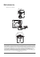
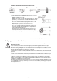
Dimensions All dimensions are in millimeters 116° 116° 140 390 133 360 332 249 71 Min. c/c 330 196 270° 270° 302 ©2011-2013 Martin Professional A/S. Information subject to change without notice. Martin Professional A/S and all affiliated companies disclaim liability for any injury, damage, direct or indirect loss, consequential or economic loss or any other loss occasioned by the use of, inability to use or reliance on the information contained in this manual.
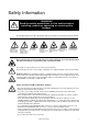
Safety Information WARNING! Read the safety precautions in this section before installing, powering, operating or servicing this product. The following symbols are used to identify important safety information on the product and in this manual: DANGER! Safety hazard. Risk of severe injury or death. DANGER! Hazardous voltage. Risk of lethal or severe electric shock. WARNING! Fire hazard. WARNING! LED light emission. Risk of eye injury. WARNING! WARNING! Burn hazard. Hot Wear protective surface.
• Refer any service operation not described in this manual to a qualified technician. • Socket outlets used to supply MAC Aura fixtures with power or external power switches must be located near the fixtures and easily accessible so that the fixtures can easily be disconnected from power. PROTECTION FROM BURNS AND FIRE • Do not operate the fixture if the ambient temperature (Ta) exceeds 40° C (104° F). • The exterior of the fixture becomes hot during use. Avoid contact by persons and materials.
Contents Dimensions . . . . . . . . . . . . . . . . . . . . . . . . . . . . . . . . . . . . . . . . . . . . . . . . . . . . . . . . . . . . . . . . . . . . . . . . 2 Safety Information . . . . . . . . . . . . . . . . . . . . . . . . . . . . . . . . . . . . . . . . . . . . . . . . . . . . . . . . . . . . . . . . . . 3 Fixture overview . . . . . . . . . . . . . . . . . . . . . . . . . . . . . . . . . . . . . . . . . . . . . . . . . . . . . . . . . . . . . . . . . . . 6 Introduction . . . . . . . . . . . . . .
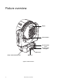
Fixture overview Display Control buttons AC mains power input AC mains power throughput DMX output Safety cable attachment point DMX input Figure 1: Fixture overview 6 MAC Aura user manual
Introduction Thank you for selecting the MAC Aura™, an intelligent lighting fixture from Martin Professional™.
AC power Warning! Read “Safety Information” starting on page 3 before connecting the MAC Aura to AC mains power. Warning! For protection from electric shock, the MAC Aura must be grounded (earthed). The power distribution circuit must be equipped with a fuse or circuit breaker and ground-fault (earth-fault) protection.
Installing a power input connector on a power cable Housing Insert Chuck To install a Neutrik PowerCon NAC3FCA input connector on a power cable: 1. Slide the bushing over the cable. 2. Slide the white chuck over cables with a diameter (Da) of 5 - 10 mm (0.2 - 0.4 in.), or the black chuck over cables with a diameter of 10 15 mm (0.4 - 0.6 in.). 3. Prepare the end of the cable by stripping 20 mm (0.8 in.) of the cable’s outer jacket. 4. Strip 8 mm (1/3 in.) from the end of each of the wires. 5.
Data link A DMX 512 data link is required in order to control a MAC Aura via DMX. The MAC Aura has 5-pin XLR connectors for DMX data input and output. The pin-out on all connectors is pin 1 = shield, pin 2 = cold (-), and pin 3 = hot (+). Pins 4 and 5 in the 5-pin XLR connectors are not used in the MAC Aura but are available for possible additional data signals as required by the DMX512-A standard. Standard pin-out is pin 4 = data 2 cold (-) and pin 5 = data 2 hot (+).
Physical installation Warning! The MAC Aura must be either fastened to a flat surface such as a stage or wall, or clamped to a truss or similar structure in any orientation using a rigging clamp. Do not apply power to the MAC Aura if it is standing freely or the fixture can be moved. Warning! If the MAC Aura can cause injury or damage it if falls, attach an approved safety cable to one of the safety cable attachment points on the base (see “Fixture overview” on page 6).
In st al M 12 b W Se olt a e wh rni U en ng se r M su ! s an pe ua nd l! ing fix tu re . To clamp a MAC Aura to a truss: 1. Check that the rigging structure can support at least 10 times the weight of all fixtures and equipment to be installed on it. 2. Obtain a rigging clamp such as the G-clamp (P/N 91602003), Half-coupler clamp (P/N 91602005) or Quick trigger clamp (P/N 91602007) Figure 3: Rigging clamp bolt available as accessories from Martin. An omega bracket is not required. 3.
Setup Warning! Read “Safety Information” on page 3 before installing, powering, operating or servicing the MAC Aura. Control panel and menu navigation The onboard control panel and backlit graphic display are used to set the MAC Aura’s DMX address, configure individual fixture settings, read out data and execute service utilities. See “Onboard control menus” on page 29 for a complete list of menus and commands.
Standard mode When the MAC Aura is set to STD standard mode, the Beam DMX channels 1 - 14 control the output of both the Beam and the Aura. The behavior of the Beam and Aura are identical. Extended mode When the MAC Aura is set to EXT extended mode: • Independent control of the Beam is available on channels 1 - 14 • A range of FX (pre-programmed effects with combined Beam and Aura output) is available on channels 15 - 19 • Independent control of the Aura is available on channels 20 - 25.
Dimming DMX % Optically linear DMX % Square law Output Output Output Output DIMMER CURVE provides four dimming options (see Figure 4): DMX % Inverse square law DMX % S-curve Figure 4: Dimming curve options • • • • LINEAR – the increase in light intensity appears to be linear as DMX value is increased. SQUARE LAW – light intensity control is finer at low levels and coarser at high levels. INVERSE SQUARE LAW – light intensity control is coarser at low levels and finer at high levels.
Operation and effects Warning! Read “Safety Information” starting on page 3 before installing, powering, operating or servicing the MAC Aura. See “DMX protocol” on page 22 for a full list of the DMX channels and values required to control the different effects.
Color wheel priority The color wheel effect channels for the Beam and Aura have priority and override any color set on the Beam RGBW channels or on the Aura RGB channels. To use the RGBW and RGB channels, you must set the color wheel effect channel for Beam or Aura respectively to a DMX value from 000 - 009. If you set either color wheel channel to a DMX value above 009, the color wheel effect overrides RGBW or RGB control.
Sync shift The sync shift option modifies FX synchronization so that FX2 runs with a time offset. This means that the FX2 cycle start point is delayed relative to FX1, but the amount of the delay remains constant. Random operation Selecting random operation makes random changes in the duration of those FX effects that have repeat cycles. This means that some cycles are shorter and some cycles are longer in a random pattern. The random sync option changes the duration of FX repeat cycles in a random pattern.
Service and maintenance Warning! Read “Safety Information” on page 3 before servicing the MAC Aura. Warning! Disconnect the fixture from AC mains power and allow to cool for at least 10 minutes before handling. Do not view the light output from less than 8.3 meters (27 ft. 3 inches) without shade 4-5 welding goggles. Be prepared for the fixture to light suddenly if connected to power. Warning! Refer any service operation not described in this user manual to a qualified service technician.
Warning! Disconnect from power and allow to cool before cleaning. To clean the fixture: 1. Disconnect the fixture from power and allow it to cool for at least 10 minutes. 2. Vacuum or gently blow away dust and loose particles from the outside of the fixture and the air vents at the back and sides of the head and in the base with low-pressure compressed air. 3. Clean the LED lens array in the front of the head by wiping gently with a soft, clean lint-free cloth moistened with a weak detergent solution.
Fixture readouts DMX input signal The DMX LIVE menu lets you view the DMX values received on each channel in the mode – STD or EXT – it is currently set to. If the fixture does not behave as expected, reading the DMX values can help you troubleshoot the problem. Fixture status The MAC Aura gives fixture status readouts in the INFO menu: • Current software/firmware version information. • Temperature readouts from the main PCB as well as the Beam LED and Aura LED PCBs.
DMX protocol Channel DMX value Percent Function Fade status Default value 0 - 19 20 - 24 25 - 64 65 - 69 70 - 84 85 - 89 90 - 104 105 - 109 110 - 124 125 - 129 130 - 144 145 - 149 150 - 164 165 - 169 170 - 184 185 - 189 190 - 204 205 - 209 210 - 224 225 - 229 230 - 244 245 - 255 0-7 8-9 10 - 25 26 - 27 28 - 33 34 - 35 36 - 41 42 - 43 44 - 49 50 - 51 52 - 57 58 - 59 60 - 65 66 - 67 68 - 73 74 - 75 76 - 81 82 - 83 84 - 89 90 - 91 92 - 97 98 - 100 Beam electronic shutter effect Shutter closed Shutter o
Channel Std. Ext.
Channel DMX value Percent Fade status Default value 0-9 10 - 14 15 - 19 20 - 24 25 - 29 30 - 34 35 - 39 40 - 44 45 - 49 50 - 54 55 - 59 60 - 64 65 - 69 70 - 74 75 - 79 80 - 84 85 - 89 90 - 94 95 - 99 100 - 104 105 - 109 110 - 114 115 - 119 120 - 124 125 - 129 130 - 134 135 - 139 140 - 144 145 - 149 150 - 154 155 - 159 160 - 164 165 - 169 170 - 174 175 - 179 0-2 3- 4 4-5 6-7 8-9 10 - 11 12 - 13 14 - 15 16 - 17 18 - 19 20 - 21 22 - 23 24 - 25 26 - 27 28 - 29 30 - 31 32 - 33 34 - 35 36 - 37 38 - 39 40 -
Channel Std. Ext.
Channel Std. - Ext.
FX: pre-programmed effects The table below lists the pre-programmed effects that can be selected on DMX channels 15 and 17. Two effects can be superimposed by selecting one effect on channel 15 and a different effect on channel 17.
LEE colors and RGB equivalents The table below gives approximate RGB equivalents for the LEE colors available in the standard MAC Aura’s color wheel effects for the Beam (on DMX channel 9 in STD and EXT modes) and Aura (on DMX channel 22 in EXT mode only). DMX Integer Lee no.
Onboard control menus Menu Item DMX ADDRESS CONTROL MODE COLOR CALIB Options 1 – XXX STD EXT ON OFF P/T SPEED P/T SETTING FANS DIMMER CURVE DIMMER SPEED PERSONALITY DMX RESET SWAP PAN INVERT TILT INVERT REGULATED FULL LINEAR SQUARE LAW INV SQUARE LAW S-CURVE FAST SMOOTH OFF ON ON 2MIN DISPLAY 5MIN 10MIN DISPLAY INTENSITY ERROR MODE 10-100 NORMAL SILENT FACTORY SETTING FACTORY DEFAULT LOAD Notes (Default settings in bold print) DMX address (default address = 1).
Menu Item Options VERSION POWER ON HOURS MAIN PCB TEMP RESETTABLE TOTAL CLEAR RESETTABLE CURRENT SINCE RESET MAX CURRENT INFO BEAM LED TEMP RESET MAX CURRENT AURA LED TEMP RESET MAX SERIAL NUMBERS TEST DMX LIVE TEST ALL TEST LEDS TEST MOTORS TEST DISPLAY RATE QUALITY START CODE BEAM SHUT AURA BLUE SERVICE P/T FEEDBACK CALIBRATION RDM FIXT SERIAL NUMBER xx Hz 0 - 100% 0 - 255 0 - 255 ON OFF PAN OFFSET TILT OFFSET Notes (Default settings in bold print) CPU firmware version Hours of operatio
Display messages Message Appears when... What to do... RST (Reset) ... the fixture is indexing effects at startup. Wait for reset to complete. SRST (Serial reset) ... the fixture has received a reset command. Wait for reset to complete. Note that you can set PERSONALITY → DMX RESET to OFF to prevent accidental DMX reset commands. MEMORY ERROR ...the EEPROM memory cannot be read. Reset fixture. Contact Martin if problem persists. MAIN TMP SEN ERR (RDM message: Head Temp. Error) ...
Troubleshooting Problem Fixture is completely dead. One or more fixtures resets correctly but responds erratically or not at all to the controller. Light output shuts down unexpectedly. Probable cause(s) Remedy No power to fixture. Check AC mains power and connections. Internal circuit fault. Have faulty fixture serviced by Martin service technician. Fault on data link. Inspect connections and cables. Correct poor connections. Repair or replace damaged cables. Data link not terminated.
Specifications Physical Length . . . . . . . . . . . . . . . . . . . . . . . . . . . . . . . . . . . . . . . . . . . . . . . . . . . . . .302 mm (11.9 in.) across yoke Width . . . . . . . . . . . . . . . . . . . . . . . . . . . . . . . . . . . . . . . . . . . . . . . . . . . . . . .302 mm (11.9 in.) across yoke Height . . . . . . . . . . . . . . . . . . . . . . . . . . . . . . . . . . . . . . . . . . . . . . . . . . 360 mm (14.2 in.), head straight up Weight . . . . . . . . . . . . . . . . . . . . . . . . .
Electrical AC power . . . . . . . . . . . . . . . . . . . . . . . . . . . . . . . . . . . . . . . . . . . . . . . . . . . . 100-240 V nominal, 50/60 Hz Maximum total power consumption . . . . . . . . . . . . . . . . . . . . . . . . . . . . . . . . . . . . . . . . . . . . . . . . . . .260 W Power supply unit. . . . . . . . . . . . . . . . . . . . . . . . . . . . . . . . . . . . . . . . . Auto-ranging electronic switch mode Power consumption, all effects static, zero light output . . . . . . . . . . . . . . .
www.martin.