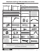
Manchester Split-top Table Assembly Instructions Parts List Part A - 1 piece Part B - 1 piece Part C - 1 piece Part D - 1 piece Part E - 1 piece Part G - 1 piece Part H - 1 piece Part F - 1 piece Part I - 1 piece Part J - 1 piece Part K - 4 pieces Part L - 1 piece Part M - 2 pieces Part N - 10 pieces Part O - 4 pieces Part P - 3 pieces 6x50mm Part Q - 2 pieces Part R - 3 pieces 4x18mm 6x30mm Part T- 4 pieces Part S - 14 pieces 4x30mm 6x8mm 4x12mm Part U - 2 pieces Part V - 4 pieces
Manchester DRAWER Assembly PLEASE NOTE: Assemble the Drawer FIRST before assembling the base. Once assembled, set drawer to side. Assembled drawer to be used later during assembly of table. STEP 1] Assemble Drawer FIG A K Y Begin by taking the back panel of drawer (Part Y) and inserting 1 plastic T-nut (part K) into each hole, making sure the hole in the T-nut is lined up with the hole in the edge of the back panel. See FIG A. K STEP 2] Assemble Drawer, cont’d.
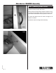
Manchester DRAWER Assembly STEP 4] Assemble Drawer, cont’d Attach sides of drawers (Parts A1L & A1R) to the Drawer front (Part Z) by inserting Threaded Connection Pins into the holes on the outside edge of the Drawers sides (Parts A1L & A1R). A1L PLEASE NOTE: The Grooves in each side must be lined up with each other to allow the drawer bottom to be installed. KZ FIG D To secure, tighten the T-nuts found on the outer side of the drawer sides. Turn the T-nuts until tight.
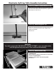
Manchester DRAWER Assembly STEP 7] Attaching Drawer Handle Attach drawer handle (Part L) to drawer, using 2 each 4x18mm screws (Part Q). See FIG H Insert screws (Part Q) through inside of drawer into appropriate holes and tighten with phillips screwdriver. Hold onto drawer handle while securing screws. See FIG I L Z Go back and double check all screws are tight on all sections of drawer. Set Drawer aside and begin table assembly. FIG H FIG I Z May 08- RPI Q Pg.
Manchester Split-top Table Assembly Instructions STEP 1] Assembly Base of Table N C A FIG 1 PLEASE NOTE: The Black square caps as shown in FIG 1 indicate the top side of Parts A & B D A Begin by assembling the base by taking the left side (part A) and attaching the three cross supports (part C, D & E) using 1 each 6x50mm hex bolts (part N) into each hole found on the outside side edge of Part A and lining that hole up with the hole in the end of each cross support.
Manchester Split-top Table Assembly Instructions STEP 3] Assembly Base of Table, cont’d C N FIG 5 Repeat with right side (part B) by attaching the other end of the three cross supports (part C, D & E) using 1 each 6x50mm hex bolts (part N) into each hole found on the outside side edge of Part A and lining that hole up with the hole in the end of each cross support. Tighten hex bolt with Allen Wrench (part C1).
Manchester Split-top Table Assembly Instructions STEP 5] Attach Lower Cross support N Attach lower wider Cross Support (part F) to lower portion of base by lining up the two holes on each end of Part A & B with the two holes found in each end of Part F. Secure by using two each 6x50mm Hex Bolts in each end. SEE FIG 9. PLEASE NOTE: DO NOT OVERTIGHTEN HEX BOLT to cause frame to bend.
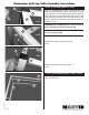
Manchester Split-top Table Assembly Instructions STEP 8] Attach Drawer support guide Attach Drawer support guide (Part G) to base cross supports (part C & E) using 2 each 6x30mm Hex bolts. Tighten with Allen Wrench. See FIG 12. E PLEASE NOTE: Make sure the Drawer Support guide is facing the right as in FIG 12.
Manchester Split-top Table Assembly Instructions STEP 11] Attach Tilt Mechanism to Top After lining up holes, attach tilt mechanism (Part J) to top with 2 each 6x8mm Hex Bolts (Part P). Tighten with Allen Wrench. See FIG 15. J FIG 15 STEP 12] Attach Hinges to Top Attach the 2 Hinges (Part M) to the top by using 3 each 4x12mm screws (Part S) per hinge. Tighten with phillips screwdriver. See FIG 16.
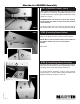
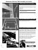
Manchester Split-top Table Assembly Instructions STEP 14] Attaching Drawer Stop, cont’d After sliding Drawer into table, you need to install the drawer stop (Part X). This can be a bit tricky. You need to position the Drawer Stop (Part X) as shown in FIG 18 and FIG 18b, then from underneath, secure the drawer stop with a 6x8mm Hex Bolt (Part P). Tighten with the allen wrench. X P FIG 18 D X FIG 18b P If installed correctly, the Drawer will not be able to be pulled all the way out of the table.
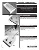
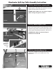
Manchester Split-top Table Assembly Instructions WARNING: To Install the SIDE SHELF, the Table must be turned back over onto its Table Top. Use 2 People to turn Table over onto the Table Top, making sure it is placed on a protected surface like a carpeted floor. STEP 15] Attaching Side Shelf NOTE: The photo at the left show the table laying top down on the carpeted floor and standing above the table looking downward.
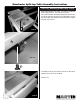
Manchester Split-top Table Assembly Instructions FIG 21 STEP 16] Attaching Side Shelf Once Side Shelf is positioned correctly, secure shelf using 3 wood 4x30mm screws (Part R) in the holes indicated in FIG 21. Use a Phillips Screwdriver to secure. DO NOT OVER TIGHTEN - This will cause the screws to be loose. Secure with screws in the indicated holes WARNING: Your Table needs to be turned back onto its legs. Use 2 people to carefully turn the table back over onto its legs.