
User guide

Martin MST IDLER BUSHING
MOUNTING INSTRUCTIONS
(contʼd)
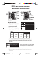
6. Tighten cap screws sequentially,
progressing in small stages until
they are tightened to the proper
torque. (see Table B).
7. Make sure there is a gap between the bushing ange and the idler product
face. If there is no gap, disassemble the parts and determine the reason
for the faulty assembly.
8. Install shoulder bolt into mounting bracket. Tighten shoulder bolt into
bracket (tapped style bracket), or tighten outer jam nut (plain style hole
bracket) to torque limit shown in Table A.
9. Make sure all drive components are aligned properly (see Fig. 3).
REMOVAL:
1. Remove cap screws.
2. Place cap screws in threaded bushing ange holes.
3. Tighten cap screws against the idler product face until screw force releases
the idler product from the idler bushing.
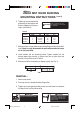
TABLE B
Idler
SAE Grade 5 Cap Screws Tightening Torque
Bushing
Number Size
lb-in N-m
H-BB 1/2 2 1/4-20NC 95 10.7
P1-BB 5/8 3 5/16-18NC 192 21.7
Q1-BB 3/4 3 3/8-16NC 348 39.3
Q1-BB 1 3 3/8-16NC 348 39.3
Mounting_Bushings.indd 4/16/03, 12:20 PM3