
Instruction Manual

Rotational Vacuum Concentrator RVC 2-33 IR
5 Set-up and connection
30
Version 08/2009, Rev. 2.1 of 02/12/2014 • sb
Translation of the original operating manual
Pos: 101 /20 0 Ch rist/3 70 RV C-B A (S TAN DAR DMODU LE) /05 0 Aufstel l ung und A nschlus s /05 0-0060 Ansc hl uss vo n Vak uump um pe u nd/o der K ühlfall e @ 2 5\m od_140 498 5088 297 _68 .docx @ 1 8706 5 @ 2 @ 1
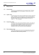
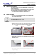
5.6 Connection of a vacuum pump and/or a cooling trap
In order to withdraw and condense the vapours that are formed, the RVC
can be connected with further components.
Pos: 102 /01 0 Uni v ersal mod ule/L eerz ei le @ 0\m od_ 120 211624 450 0_0. doc x @ 11 4 @ @ 1
Pos: 103 /20 0 Ch rist/ 371 R VC-B A (P ROJE K TE)/R VC 2- 33 IR /05 0 Auf st ellung und Ansc hlus s/05 0-0 060 -00 10 A bpu mpen de r Dä mpf e üb er Vak uum pu mpe RVC 2-3 3 IR @ 31\ mod _14 074 840669 61_ 68.d ocx @ 209 056 @ 3 @ 1
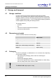
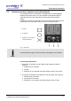
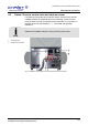
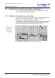
5.6.1 Withdrawal of the vapours by a vacuum pump
The vapours are withdrawn by a vacuum pump, e.g. the vacuum diaphragm
pump for chemical applications”MZ 2C” or “MD 4C”, followed by
condensation in a liquid-cooled emission condenser.
This application is suitable for low-boiling samples containing solvents. The
vacuum pump must be connected to the RVC. The connector of the stop
valve must be plugged into the socket on the back of the unit.
1 RVC
2 Vacuum sensor
3 Stop valve
4 Vacuum hose
5 Vacuum pump
Fig. 9: Combination of the RVC with a vacuum pump and a stop valve
Pos: 104 /01 0 Uni v ersal mod ule/S eit enwec hsel @ 0\m od_ 120 211 624 4312 _0. docx @ 10 5 @ @ 1