
Instruction Manual

Rotational Vacuum Concentrator RVC 2-33 IR
2 Layout and mode of operation
Version 08/2009, Rev. 2.1 of 02/12/2014 • sb
11
Translation of the original operating manual
Pos: 17 / 200 Chri st /37 0 RVC -BA (STAN DAR DM ODU LE)/ 020 Au fba u un d Wi rku ngsw ei se/0 20 A ufba u un d Wirk ungs w eise= == == ===== == ===== == ===== == = @ 25\m od_ 140 498 497 7875 _68 .docx @ 1 865 89 @ 1 @ 1
2 Layout and mode of operation
Pos: 18 / 200 Chris t/ 370 R VC-B A (S TANDA RDM OD ULE)/ 020 A u fba u und W irku ngsw eis e/0 20-001 0 Auf bau des R otat i ons-Vak uu m-K onz ent rators ---- -- ----- ----- --- ----- --- ----- ----- --- --- @ 2 5\m od_ 140 498 4978 712_68 .doc x @ 1 8660 3 @ 2 @ 1
2.1 Layout of the RVC
Pos: 19 / 200 Chris t /37 1 RVC -BA (P ROJE KTE )/ RVC 2-33 IR / 020 Au fba u un d Wirk ungsw eis e/0 20-001 0-0 010 Funk tio ns- und B edien el ement e R VC 2- 33 IR @ 3 1\mo d_1 407 484 032 340_68. doc x @ 20 8928 @ 3 @ 1
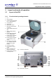
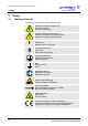
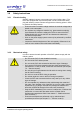
2.1.1 Functional and operating elements
1 Lid
2 Rotor chamber
3 Control panel (see chapter
6.5.1 - "User interface")
4 Lid lock device
5 Rotor shaft
6 Mains power switch
7 Electrical vacuum sensor
connection
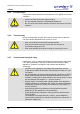
8 Option: Serial Interface RS
232
9 Option: Serial Interface
Remote
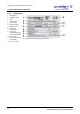
10 Name plate (see chapter
2.1.2 - "Name plate")
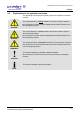
11 Power supply connection
of the vacuum pump
12 Power supply connection
of the pressure control
valve
13 Valve block (see chapter
5.3 - "Aeration and micro
injection valve (Valve
block)")
14 Vacuum connection
15 Equipotential bonding
screw
16 Mains connection and
mains fuse protection
17 Power supply connection
of the stop valve
Fig. 1: Total view of the RVC
Fig. 1: Rear view of the RVC
Pos: 20 / 010 U nive rsalm odul e/S eite nwechs el @ 0 \mo d_1 202116 244 312_ 0.d ocx @ 105 @ @ 1