
Owner manual

RVC 2-25 CD&
5 Set-up and connection
30
Version 11/2008, Rev. 2.2 of 04/12/2013 • sb
Translation of the original operating manual
Pos: 102 /20 0 Ch rist /3 70 RVC -BA (S TAN DAR DMODU LE) /05 0 Aufst ell ung und Anschl us s/05 0-0 060 A nschl us s vo n Vaku ump um pe u nd/o der K ühlfall e @ 8 \mo d_1 309 3374394 43_ 68. docx @ 46 677 @ 2 @ 1
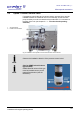
5.6 Connection of a vacuum pump and/or a cooling trap
In order to withdraw and condense the vapours that are formed, the RVC
can be connected with further components.
Pos: 103 /01 0 Univ ersal module/ Lee rzeile @ 0\ mo d_12021 162445 00_ 0.docx @ 1 14 @ @ 1
Pos: 104 /20 0 Ch rist/3 71 RV C-BA (PRO JEK TE )/RV C 2-25 C D plus/0 50 Auf s tellu ng u nd Ansc hl uss/ 050 -0060- 0010 Abp ump en der anf allend en Dä mpf e ü ber ei ne V akuu mpu mpe @ 8\ mo d_1 3159 017920 34_ 68.d ocx @ 505 13 @ 3 @ 1
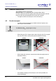
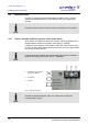
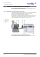
5.6.1 Withdrawal of the vapours by a vacuum pump
The vapours are withdrawn by a vacuum pump, e.g. the vacuum diaphragm
pump for chemical applications”MZ 2C” or “MD 4C”, followed by
condensation in a liquid-cooled emission condenser.
This application is suitable for low-boiling samples containing solvents. The
vacuum pump must be connected to the RVC. The connector of the stop
valve must be plugged into the socket on the back of the unit.
1 Vacuum hose
2 Vacuum pump
3 Stop valve
4 RVC
Fig. 10: Combination of the RVC with a vacuum pump and a stop valve
Attention: The set-up in the photo is for demonstration purposes only! Normally, the stop
valve is installed behind the RVC and cannot be seen from the front.
Pos: 105 /01 0 Univ ersal module/ Sei tenwe chsel @ 0\ mod_12 0211624 4312_0 .docx @ 105 @ @ 1