
Owner manual

RVC 2-25 CD&
2 Layout and mode of operation
Version 11/2008, Rev. 2.2 of 04/12/2013 • sb
11
Translation of the original operating manual
Pos: 17 / 200 C hrist /37 0 RV C-B A (S TANDA RD MO DULE )/ 020 Au fba u un d Wi rku ngsw ei se/0 20 A ufba u un d W irk ungsw ei se= == ===== == ===== == ===== == == = @ 7\ mod_1 309 255 680 878_ 68. docx @ 46 261 @ 1 @ 1
2 Layout and mode of operation
Pos: 18 / 200 Chri st /37 0 RVC -BA (STAN DAR DM ODU LE)/ 020 Au fba u un d Wi rku ngsw ei se/0 20- 0010 A uf bau des R otati ons-V ak uu m-Konz ent rato rs- --- -- ----- ----- --- ----- --- ----- --- ----- -- - @ 7\ mod_1 309 255 6817 37_ 68. docx @ 46 277 @ 2 @ 1
2.1 Layout of the RVC
Pos: 19 / 200 Chris t /37 1 RVC -BA (P ROJE KTE )/R VC 2-2 5 CD pl us/02 0 Aufb au und Wi rkun gsw eise /020 -0 010 -0010 Fun ktions - u nd Bedi enel eme nte @ 7\ mod _130925 216 173 8_6 8.doc x @ 4 615 0 @ 3 @ 1
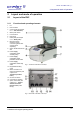
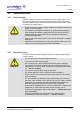
2.1.1 Functional and operating elements
1 Lid
2 Rotor chamber
3 Control panel (see chapter
6.5.1 - "User interface")
4 Mains power switch
5 Lid lock device
6 Rotor shaft
7 Name plate (see chapter
2.1.2 - "Name plate")
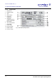
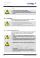
8 Electrical vacuum
measuring sensor
connection (please order
vacuum sensor
separately)
9 Option: Serial Interface RS
232
10 Power supply
connection of the
vacuum pump
11 Power supply
connection of the
pressure control valve
12 Power supply
connection of the stop
valve
13 Equipotential bonding
screw
14 Mains connection and
mains fuse protection (see
chapter 5.2.2 -
"Customer-provided
fuses")
15 Vacuum connection
16 Connection for aeration
17 Option: Valve block (see
chapter 5.3.1 - "Option:
Aeration and micro
injection valve (Valve
block)")
Fig. 1: Total view of the RVC 2-25 CD
plus
Fig. 1: Rear view of the RVC 2-25 CD
plus
Pos: 20 /010 Unive rsalm odule/ Seit enwec hsel @ 0\m od_120 2116244 312_0. docx @ 105 @ @ 1