
User guide

RVC 2-18 CD& HCL
5 Set-up and connection
30
Version 04/2012, Rev. 1.4 of 25/11/2013 • sb
Translation of the original operating manual
Pos: 101 /20 0 Ch ris t/3 71 RVC -BA (PROJ EK TE)/R VC 2- 18 CD plus_ 2-1 8 CD plus _HC l/05 0 Auf st ellun g un d A nschl uss /0 50-006 0-0 040 PR OFESS IONA L TWIN: K o nde nsatio n üb er eine K ühl falle mi t zw ei RV C HC l @ 1 2\m od_ 133 533 260 0357_68 .doc x @ 6 402 1 @ 3 @ 1
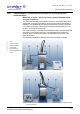
5.5.4 PROFESSIONAL TWIN: Condensation of the vapours in a cooling trap with
distributor block and two RVCs
With two RVC 2-18 CD
plus
HCl and a cooling trap with distributor block
and glass cooling trap
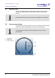
The characteristic feature of a rotational vacuum concentrator (RVC) is the
combination of vacuum and rotation. During the process, a gas volume is
released. The released vapours that are carried off by the RVC condenser
in the glass cooling trap. This glass cooling trap is located inside a CT 02-
50 SR or CT 04-50 SR cooling trap.
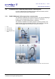
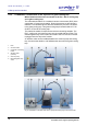
The vacuum pump is connected to the distributor block. An electromagnetic
stop valve is connected to each of the RVCs. The distributor block includes
an aeration valve. It ensures the aeration and facilitates the removal of the
glass cooling trap.
The method is suitable for aqueous and solvent-containing samples.
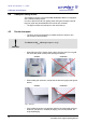
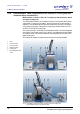
1 RVC
2 Vacuum pump
3 Vacuum hoses
4 Distributor block
5 Cooling trap
6 Electromagnetic stop
valve
Fig. 4: Combination of two RVCs with a vacuum pump and cooling trap
with a distributor block, front and rear view
Pos: 102 /01 0 Univ ersal module/ Sei tenwe chsel @ 0\ mod_12 0211624 4312_0 .docx @ 105 @ @ 1