
User guide

RVC 2-18 CD& HCL
5 Set-up and connection
Version 04/2012, Rev. 1.4 of 25/11/2013 • sb
29
Translation of the original operating manual
Pos: 99 / 200 Christ /37 1 RV C-BA (PROJE KTE )/R VC 2-1 8 CDpl us_2 -18 CD pl us_HCl /050 A ufstell ung und Anschl uss /05 0-0 060-00 30 PRO FE SSI ONAL: K o ndens atio n über eine K ühl falle mit V ertei le rblock @ 1 2\mo d_1335 260 055 746 _68. docx @ 64007 @ 3 @ 1
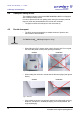
5.5.3 PROFESSIONAL: Condensation of the vapours in a cooling trap with
distributor block
With a RVC 2-18 CD
plus
HCl and a cooling trap with distributor block
and glass cooling trap
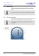
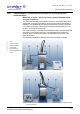
The characteristic feature of a rotational vacuum concentrator (RVC) is the
combination of vacuum and rotation. During the process, a gas volume is
released. The released vapours that are carried off by the RVC condenser
in the glass cooling trap. This glass cooling trap is located inside a CT 02-
50 SR or CT 04-50 SR cooling trap.
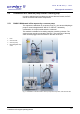
The vacuum pump is connected to the distributor block. An electromagnetic
stop valve is connected to the RVC. The distributor block includes an
aeration valve. It ensures the aeration and facilitates the removal of the
glass cooling trap.
This method is suitable for aqueous and solvent-containing samples.
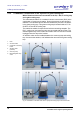
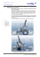
1 RVC
2 Vacuum hoses
3 Distributor block
4 Cooling trap
5 Vacuum pump
6 Electromagnetic stop
valve
Fig. 3: Combination of the RVC with a vacuum pump and cooling trap with a distributor block
front and rear view
Pos: 100 /01 0 Univ ersal module/ Sei tenwe chsel @ 0\ mod_12 0211624 4312_0 .docx @ 105 @ @ 1