
User guide

RVC 2-18 CD& HCL
5 Set-up and connection
Version 04/2012, Rev. 1.4 of 25/11/2013 • sb
27
Translation of the original operating manual
Pos: 93 / 200 Christ /37 0 RV C-B A (STA NDA RDM ODU LE)/ 050 Au fstel lu ng u nd Ans chlus s/ 050 -0060 A nsc hluss von V ak uumpu mp e un d/od er Kü hlfall e @ 8\ mod _13 093 374 3944 3_68.d ocx @ 466 77 @ 2 @ 1
5.5 Connection of a vacuum pump and/or a cooling trap
In order to withdraw and condense the vapours that are formed, the RVC
can be connected with further components.
Pos: 94 /010 Unive rsalm odule/ L ee rzeile @ 0\ mod _120211 624450 0_0.docx @ 11 4 @ @ 1
Pos: 95 / 200 Chri st /37 1 RV C-BA (PR OJEK TE) /RV C 2-1 8 CDpl us_2 -18 CD plus _HCl /050 A ufstel l ung und A nschl uss /05 0-0 060 -00 11 BAS IC: A b pum pen über ei ne Vak uum pum pe_HC L @ 12\ mod_ 133 525 318 202 0_68. docx @ 6 399 1 @ 3 @ 1
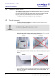
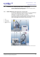
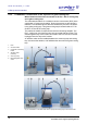
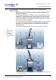
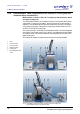
5.5.1 BASIC: Withdrawal of the vapours by a vacuum pump
The vapours are withdrawn by a vacuum pump, e.g. the vacuum diaphragm
pump for chemical applications "MZ 2C" or "MD 4C", followed by
condensation in a liquid-cooled emission condenser.
This method is suitable for low-boiling samples containing solvents. The
vacuum pump must be connected to the RVC. The connector of the stop
valve must be plugged into the socket on the back of the unit.
1 RVC
2 Vacuum hose
3 Vacuum pump
4 Electromagnetic stop
valve
Fig. 7: Combination of the RVC with a vacuum pump and a stop valve, front and rear view
Pos: 96 /010 Unive rsalm odule/ Seit enwec hsel @ 0\m od_120 2116244 312_0. docx @ 105 @ @ 1