Operating Manual Rotational Vacuum Concentrator RVC 2-18 CD& HCL Part no. 100246 Part no. Ref. Translation of the original operating manual A sb Version 04/2012 Rev. 1.
RVC 2-18 CD& HCL 2 Version 04/2012, Rev. 1.
RVC 2-18 CD& HCL In case of inquiries, please state the following numbers: Order number Serial number © Copyright by Martin Christ Gefriertrocknungsanlagen GmbH An der Unteren Söse 50 37520 Osterode am Harz Germany Tel.: +49 (0) 5522 / 5007-0 Fax: +49 (0) 5522 / 5007-12 Web: www.martinchrist.de E-mail: info@martinchrist.de Version 04/2012, Rev. 1.
RVC 2-18 CD& HCL Table of contents 1 General information ............................................................................................................. 9 1.1 Importance of the operating manual.................................................................................. 9 1.2 Intended use ..................................................................................................................... 9 1.3 Warranty and liability..................................................
RVC 2-18 CD& HCL Table of contents 5 Set-up and connection ...................................................................................................... 25 5.1 Installation site ................................................................................................................ 25 5.2 Power supply .................................................................................................................. 25 5.2.1 Connection .....................................................
RVC 2-18 CD& HCL Table of contents 8 Maintenance and service................................................................................................... 53 8.1 Maintenance ................................................................................................................... 53 8.1.1 Rotational vacuum concentrator ................................................................................ 53 8.1.2 Rotor chamber .......................................................................
RVC 2-18 CD& HCL 1 General information Pos: 1 /2 00 C hrist/ 370 RVC -BA (STANDARDMODU LE)/0 10 Allge mein e Inf or matio nen/ 010 Allge meine Inf orm ation en === == == === == == === == == == === == == == @ 8\m od_ 131 597 778 493 7_68 .docx @ 5 058 1 @ 1 @ 1 1 General information Pos: 2 /2 00 C hrist/ 370 RVC -BA (STANDARDMODU LE)/0 10 Allge mein e Inf or matio nen/ 010 -00 10 Stellenw ert der B etrie bsanl eitun g @ 8\mo d_1 315 977 785 987 _68. docx @ 50 589 @ 2 @ 1 1.
RVC 2-18 CD& HCL 1 General information Pos: 8 /2 00 C hrist/ 370 RVC -BA (STANDARDMODU LE)/0 10 Allge mein e Inf or matio nen/ 010 -00 40 Urh ebe rrec ht @ 8\m od_ 131 597 7787 006 _68 .docx @ 50 613 @ 2 @ 1 1.4 Copyright The copyright concerning the operating manual remains with Martin Christ Gefriertrocknungsanlagen GmbH. The operating manual is solely intended for the operator and their personnel.
RVC 2-18 CD& HCL 1 General information Accessories and commissioning According to your order, our order confirmation, and our delivery note. Pos: 15 / 010 Unive rsalm odul e/ Absc hnittsw echsel @ 0\ mod _12 021 245 140 62_0 .docx @ 4 18 @ @ 1 Pos: 16 / 010 Unive rsalm odul e/ Seit enwec hsel @ 0\m od_ 120 211 6244 312 _0. docx @ 10 5 @ @ 1 Version 04/2012, Rev. 1.
RVC 2-18 CD& HCL 2 Layout and mode of operation Pos: 17 / 200 Christ /37 0 RVC-BA (STANDARDM ODULE)/ 020 Au fba u un d Wirku ngsw eise/0 20 A ufba u un d Wirk ungsw eise= == == === == == === == == === == == = @ 7 \mo d_1 309 255 680 878_ 68.
RVC 2-18 CD& HCL 2 Layout and mode of operation 2.1.2 1 2 3 4 5 6 7 Name plate Manufacturer Registered office Type Serial number Interference suppression CE mark in compliance with the directive 2006/42/EC Part number 8 Year of manufacture (month/year) 9 Power rating 10 Nominal voltage 11 Rated current 12 Country of origin Fig. 2: Example of a name plate (enlarged photo) Pos: 22 / 010 Unive rsalm odul e/ Seit enwec hsel @ 0\m od_ 120 211 6244 312 _0. docx @ 10 5 @ @ 1 Version 04/2012, Rev. 1.
RVC 2-18 CD& HCL 2 Layout and mode of operation Pos: 23 / 200 Christ /37 0 RVC-BA (STANDARDM ODULE)/ 020 Au fba u un d Wirku ngsw eise/0 20- 002 0 Wirk ungsw eise- -- --- -- --- -- --- --- -- --- -- --- --- -- --- -- --- -- --- --- -- --- -- @ 7\ mod _13 092 5568 523 7_6 8.do cx @ 4630 1 @ 2 @ 1 2.2 Mode of operation Pos: 24 / 200 Christ /37 0 RVC-BA (STANDARDM ODULE)/ 020 Au fba u un d Wirku ngsw eise/0 20- 002 0-0 010 Prinzip de r Rot ations -Vaku um-K onze ntra tion @ 7\ mod _13 092 5568 564 3_6 8.
RVC 2-18 CD& HCL 2 Layout and mode of operation Fig. 4: Vapour pressure curves of commonly used organic solvents Pos: 25 / 010 Unive rsalm odul e/ L ee rzeile @ 0\ mod _120 211 624 450 0_0. docx @ 11 4 @ @ 1 Pos: 26 / 200 Christ /37 0 RVC-BA (STANDARDM ODULE)/ 020 Au fba u un d Wirku ngsw eise/0 20- 002 0-0 010 -00 10 Vo rteil e de r Rot ations -Vaku um -Konze ntr ation @ 7\ mod _13 092 556 8606 5_6 8.d ocx @ 463 17 @ 4 @ 1 2.2.1.
RVC 2-18 CD& HCL 3 Safety Pos: 29 / 010 Unive rsalm odul e/ Absc hnittsw echsel @ 0\ mod _12 021 245 140 62_0 .docx @ 4 18 @ @ 1 Pos: 30 / 010 Unive rsalm odul e/ Seit enwec hsel @ 0\m od_ 120 211 6244 312 _0. docx @ 10 5 @ @ 1 Pos: 31 / 200 Christ /37 0 RVC-BA (STANDARDM ODULE)/ 030 Sich erh eit/0 30 Sic her heit= == == === == == === == == == === == == === == == @ 7\ mod _13 0933 103 683 4_6 8.
RVC 2-18 CD& HCL 3 Safety Pos: 34 / 200 Christ /37 0 RVC-BA (STANDARDM ODULE)/ 030 Sich erh eit/0 30- 002 0 Sym bol- un d Hinweis erklä run gen @ 7\ mod _13 093 310 376 15_6 8.d ocx @ 464 07 @ 2 @ 1 3.2 Explanation of the symbols and notes This operating manual uses the following names and symbols to indicate hazards: GEFAHR DANGER WARNING This symbol stands for a direct hazard to the life and health of persons.
RVC 2-18 CD& HCL 3 Safety Pos: 36 / 200 Christ /37 0 RVC-BA (STANDARDM ODULE)/ 030 Sich erh eit/0 30- 003 0 Ve rantw ort ung des Be treib ers @ 7\ mod _13 093 310 3800 5_6 8.d ocx @ 464 15 @ 2 @ 1 3.3 Responsibility of the operator The operator is responsible for authorising only qualified personnel to work on the RVC (see chapter 3.4 - "Operating personnel"). The areas of responsibility of the personnel concerning the operation, maintenance, and care of the unit must be clearly defined.
RVC 2-18 CD& HCL 3 Safety Pos: 42 / 200 Christ /37 0 RVC-BA (STANDARDM ODULE)/ 030 Sich erh eit/0 30- 006 0 Sich erh eitshinw eise- -- --- --- -- --- -- --- --- -- --- -- --- -- --- --- -- --- - @ 7\m od_ 1309 331 039 036 _68. docx @ 46 439 @ 2 @ 1 3.6 Safety instructions Pos: 43 / 200 Christ /37 0 RVC-BA (STANDARDM ODULE)/ 030 Sich erh eit/0 30- 006 0-0 010 Elektris che Sich erh eit @ 7\m od_ 130 933 1039 396 _68 .docx @ 46 447 @ 3 @ 1 3.6.
RVC 2-18 CD& HCL 3 Safety Pos: 47 / 200 Christ /37 0 RVC-BA (STANDARDM ODULE)/ 030 Sich erh eit/0 30- 006 0-0 030 Bra ndsch utz @ 7\m od_ 130 933 104 011 5_68 .docx @ 4 646 3 @ 3 @ 1 3.6.3 Fire prevention Fuses protect certain electrical circuits within the RVC against over-current conditions. • • • GEFAHR Pos: 48 / 010 Unive rsalm odul e/ Always use fuses of the same type and rating. Do not evaporate explosive or inflammable substances.
RVC 2-18 CD& HCL 3 Safety 3.6.6 Safety instructions for evaporation The following instructions must be observed prior to every evaporation process: • • WARNING • • • • Pos: 54 / 010 Unive rsalm odul e/ Ensure that the RVC was set up and connected properly (see chapter 5 - "Set-up and connection"). Maintain a safety distance of at least 30 cm (12 inches) around the RVC. Do not store any dangerous goods in the safety area of the RVC.
RVC 2-18 CD& HCL 3 Safety 3.8 Procedures in the event of hazards and accidents DANGER Fire: • A fire in the electrical control system must be extinguished with a CO2 fire extinguisher! • Burning oil must be extinguished with a CO2 fire extinguisher or powder fire extinguisher! Hazardous electrical incident: • Set the mains power switch of the control system to the "0" position in order to interrupt the power supply completely. Burns: • Small-area burns (e.g.
RVC 2-18 CD& HCL 4 Storage and transport Pos: 69 / 200 Christ /37 0 RVC-BA (STANDARDM ODULE)/ 040 Lag eru ng u nd Tra nsp ort/ 040 La ger ung und Tr ansp ort == == === == == === == == === == == == @ 7\ mod_ 130 933 471 646 4_6 8.doc x @ 4 654 9 @ 1 @ 1 4 Storage and transport Pos: 70 / 200 Christ /37 0 RVC-BA (STANDARDM ODULE)/ 040 Lag eru ng u nd Tra nsp ort/ 040 -00 10 Lag erb eding ung en @ 8\ mod_ 130 933 471 722 9_6 8.doc x @ 4 656 5 @ 2 @ 1 4.
RVC 2-18 CD& HCL 4 Storage and transport Pos: 76 / 200 Christ /37 1 RVC-BA (PROJEKTE) /RVC 2-1 8 CDpl us_2 -18 CD plus_HCl /040 La ger ung und Tr ansp ort/ 040 -00 41 Tr ans portsic her ung HCl @ 1 2\m od_ 133 697 3510 317 _68 .docx @ 6 4439 @ 2 @ 1 4.4 Transport safety device The rotational vacuum concentrator RVC 2-18 CDplus HCl is not equipped with a transport safety device.
RVC 2-18 CD& HCL 5 Set-up and connection Pos: 81 / 200 Christ /37 0 RVC-BA (STANDARDM ODULE)/ 050 Au fstellu ng u nd Ans chluss/ 050 Aufst ellung un d Anschl uss= === == == === == == === == == == == @ 8\m od_ 130 933 583 2534 _68 .docx @ 4 658 1 @ 1 @ 1 5 Set-up and connection Pos: 82 / 200 Christ /37 0 RVC-BA (STANDARDM ODULE)/ 050 Au fstellu ng u nd Ans chluss/ 050 -00 10 A ufstello rt, Eins atzo rt @ 8\m od_ 130 9335 833 534 _68 .docx @ 46 605 @ 2 @ 1 5.
RVC 2-18 CD& HCL 5 Set-up and connection Pos: 89 / 200 Christ /37 0 RVC-BA (STANDARDM ODULE)/ 050 Au fstellu ng u nd Ans chluss/ 050 -00 30 B elüftu ngsv entil @ 8\m od_ 130 941 9388 700 _68 .docx @ 4 6708 @ 3 @ 1 5.3 Aeration valve The RVC is equipped with an electromagnetic aeration valve. The rotor chamber is aerated through this valve after the end of the evaporation process. Unpressurised inert gas can also be used for aerating the rotor chamber.
RVC 2-18 CD& HCL 5 Set-up and connection Pos: 93 / 200 Christ /37 0 RVC-BA (STANDARDM ODULE)/ 050 Au fstellu ng u nd Ans chluss/ 050 -00 60 A nschluss von V akuu mpu mp e un d/od er Kü hlfalle @ 8\ mod _13 093 374 3944 3_6 8.d ocx @ 466 77 @ 2 @ 1 5.5 Connection of a vacuum pump and/or a cooling trap In order to withdraw and condense the vapours that are formed, the RVC can be connected with further components. Pos: 94 / 010 Unive rsalm odul e/ L ee rzeile @ 0\ mod _120 211 624 450 0_0.
RVC 2-18 CD& HCL 5 Set-up and connection Pos: 97 / 200 Christ /37 1 RVC-BA (PROJEKTE) /RVC 2-1 8 CDpl us_2 -18 CD plus_HCl /050 Aufstell ung und Anschluss /05 0-0 060 -00 21 S TANDARD: Kond ensa tion übe r ein e Kühlf alle_HCl @ 12\ mod _13 352 559 377 47_ 68.d ocx @ 639 99 @ 3 @ 1 5.5.
RVC 2-18 CD& HCL 5 Set-up and connection Pos: 99 / 200 Christ /37 1 RVC-BA (PROJEKTE) /RVC 2-1 8 CDpl us_2 -18 CD plus_HCl /050 Aufstell ung und Anschluss /05 0-0 060 -00 30 PRO FESSIONAL: Ko nden satio n üb er eine Kü hlfalle mit Ve rteile rblock @ 1 2\mo d_1 335 260 055 746 _68. docx @ 64 007 @ 3 @ 1 5.5.
RVC 2-18 CD& HCL 5 Set-up and connection Pos: 101 /20 0 Ch rist/3 71 RVC-BA (PROJEK TE)/RVC 2- 18 CD plus_ 2-1 8 CDplus _HCl/05 0 Aufst ellun g un d Anschl uss/0 50- 006 0-0 040 PROFESSIONAL TWIN: Ko nde nsatio n üb er eine Kü hlfalle mit zw ei RVC HCl @ 1 2\m od_ 133 533 260 035 7_68 .docx @ 6 402 1 @ 3 @ 1 5.5.
RVC 2-18 CD& HCL 5 Set-up and connection Pos: 103 /20 0 Ch rist/3 71 RVC-BA (PROJEK TE)/RVC 2- 18 CD plus_ 2-1 8 CDplus _HCl/05 0 Aufst ellun g un d Anschl uss/0 50- 007 0 Elekt rom agn etisch es Absp err ventil @ 19 \mo d_1 379 3964 654 02_ 68.d ocx @ 950 51 @ 4 @ 1 5.
RVC 2-18 CD& HCL 6 Operation Pos: 106 /20 0 Ch rist/3 70 RVC-BA (S TANDARDMODULE) /06 0 Betri eb/0 60 Bet rieb == == === == == === == == === == == === == == == === == = @ 8\mo d_1 309 426 563 173 _68. docx @ 46 735 @ 1 @ 1 6 Operation Pos: 107 /20 0 Ch rist/3 70 RVC-BA (S TANDARDMODULE) /06 0 Betri eb/0 60- 001 0 Ers te In bet rieb nah me+ ++ ++ +++ ++ ++ +++ ++ ++ +++ ++ ++ @ 8\ mod _13 094 265 6354 8_6 8.d ocx @ 4674 3 @ 2 @ 1 6.
RVC 2-18 CD& HCL 6 Operation • Follow the safety instructions and hazard warnings (see chapter 3 "Safety")! correct incorrect Fig. 10: Symmetrical loading of angle rotors Pos: 115 /01 0 Univ ersal mod ule/ Lee rzeile @ 0\ mo d_12 021 162 445 00_ 0.doc x @ 1 14 @ @ 1 Pos: 116 /20 0 Ch rist/3 70 RVC-BA (S TANDARDMODULE) /06 0 Betri eb/0 60- 004 0-0 020 Einsetz en v on Aussc hwing rot ore n @ 8 \mo d_1 309 498 6385 52_ 68. docx @ 468 15 @ 3 @ 1 6.4.
RVC 2-18 CD& HCL 6 Operation Pos: 118 /20 0 Ch rist/3 70 RVC-BA (S TANDARDMODULE) /06 0 Betri eb/0 60- 004 0-0 030 Einsetz en v on Zub ehö r @ 8 \mo d_1 309 508 120 119 _68. docx @ 46 850 @ 3 @ 1 6.4.3 Installation of accessories • • • Only use inserts that are suitable for the rotor (see chapter 11.1 "Rotor program"). In swing-out rotors, all places of a rotor must be loaded with buckets.. Always load the opposite inserts of the rotors with the same accessories and fill to avoid imbalance.
RVC 2-18 CD& HCL 6 Operation correct incorrect Fig. 12: Permissible loading of swing-out rotors with low capacity Pos: 119 /01 0 Univ ersal mod ule/ Lee rzeile @ 0\ mo d_12 021 162 445 00_ 0.doc x @ 1 14 @ @ 1 Pos: 120 /20 0 Ch rist/3 70 RVC-BA (S TANDARDMODULE) /06 0 Betri eb/0 60- 004 0-0 030 -00 10 Gefä ße @ 8\ mod _13 094 988 287 79_ 68.d ocx @ 468 22 @ 4 @ 1 6.4.3.1 Tubes • • • Pos: 121 /01 0 Univ ersal mod ule/ Load the tubes outside of the rotational vacuum concentrator.
RVC 2-18 CD& HCL 6 Operation 6.4.3.3 Buckets • Load each bucket symmetrically to its pivotal point to ensure swinging to 90° under rotation. correct incorrect at a standstill under rotation Fig. 14: Symmetrical loading of the buckets • The balance point of the loaded bucket must be located considerably below the pivotal point. If the balance point is too near the pivotal point, the loaded bucket can be levered out of the bearings.
RVC 2-18 CD& HCL 6 Operation Pos: 126 /20 0 Ch rist/3 70 RVC-BA (S TANDARDMODULE) /06 0 Betri eb/CDpl us/06 0- 0050 CDpl us Anlag enst eue run g-- -- --- --- -- --- -- --- --- -- --- -- --- -- --- --- -- -- @ 8\m od_ 130 950 863 486 7_6 8.docx @ 4 685 6 @ 2 @ 1 6.5 CDplus control system The control system CDplus (“Concentrator Display plus”) stands for a convenient user interface for the intuitive control of evaporation processes under rotation.
RVC 2-18 CD& HCL 6 Operation Values window (6) The values window is displayed after the initialisation of the CDplus control system. It is divided into two areas. Each value window is structured as follows: 9 Measuring channel 10 Set value (only shown in the run mode) 11 Unit of the measured value 12 Actual value Fig.
RVC 2-18 CD& HCL 6 Operation Operating mode (14) The rotational vacuum concentrator is in the standby mode. All aggregates are switched off. The rotational vacuum concentrator is in the run mode. The timer is deactivated. The rotational vacuum concentrator is in the run mode. The timer is activated. Active phases (15) Open lid The rotor is at a standstill, and the lid can be opened. Warm-up The vacuum pump and/or the cooling trap are in the warmup phase.
RVC 2-18 CD& HCL 6 Operation Opening the lid The lid can only be opened if the rotor is at a standstill. It is not possible to open the lid during an evaporation process During the evaporation process, the housing, lid and interior of the rotational vacuum concentrator can reach surface temperatures of more than +50°C. Risk of burns! DANGER Warm-up Before starting an evaporation process, the vacuum pump and the cooling trap should warm-up until they reach their respective operating temperatures.
RVC 2-18 CD& HCL 6 Operation Evaporation manual If the unit is in the standby mode, the evaporation phase can be started directly without a warm-up phase. For this purpose, select from the menu "Start with phase" the item "Evaporation manual". Stopping the evaporation process prematurely If the timer is active, the evaporation process will be stopped automatically when the preset time is over. The process can also be aborted manually. • Open the menu "Select mode" with the left-hand function key.
RVC 2-18 CD& HCL 6 Operation 6.5.3.1 Changing the set values for the manual mode • Select the set value with the up and down keys. The selected value is displayed in the focus. Fig. 27: Manual mode – selecting a set value • Press the right-hand function key to start the editing mode. The focus is displayed in an inverted manner. Fig. 28: The selected set value is displayed in an inverted manner • Change the set value with the up/down keys. • Press the right-hand function key "ok" to confirm.
RVC 2-18 CD& HCL 6 Operation Pos: 134 /20 0 Ch rist/3 70 RVC-BA (S TANDARDMODULE) /06 0 Betri eb/CDpl us/06 0- 0050 -00 30 -004 0 Pr ozess - un d Anla gen -Inf orm ation en @ 8\ mod _130 993 318 443 3_6 8.doc x @ 4 711 5 @ 4 @ 1 6.5.3.2 Process and equipment information The "Process & equipment Information " menu informs the user about any error, process, or system messages. In the event of a message, a sound signal can be heard and the symbol " " is displayed on the status bar.
RVC 2-18 CD& HCL 6 Operation Pos: 136 /20 0 Ch rist/3 71 RVC-BA (PROJEK TE)/RVC 2- 18 CD plus_ 2-1 8 CDplus _HCl/06 0 Bet rieb/ 060 -00 50- 003 0-0 050 Opti one n RVC 2- 18 CD plus @ 9\m od_ 132 090 6713 465 _68 .docx @ 5 4133 @ 4 @ 1 6.5.3.3 Options Fig. 30: Menu “Options” Change display contrast • Select the menu "Change display contrast". • Change the contrast by pressing the up/down keys. • Confirm the new setting by pressing the right-hand function key. Fig.
RVC 2-18 CD& HCL 6 Operation Timer warm-up You can set a warm-up time between 5 and 99 minutes. Temperature warm-up During the warm-up phase, the rotor temperature is set to the set temperature. Click at button push If this function is activated, a brief sound signal can be heard whenever a key is pressed. High temperature resolution Temperatures are displayed in the values window with a resolution of 1/10°C (instead of a resolution of 1°C).
RVC 2-18 CD& HCL 6 Operation Pos: 138 /20 0 Ch rist/3 70 RVC-BA (S TANDARDMODULE) /06 0 Betri eb/0 60- 006 0 Aussc halt en+ ++ +++ ++ ++ +++ ++ ++ +++ ++ ++ ++ + @ 8 \mo d_1 309 4265 648 76_ 68.d ocx @ 467 76 @ 2 @ 1 6.6 Switching the RVC off The RVC must be in the standby status. • Switch the RVC off by pressing the mains power switch on the righthand side panel. Pos: 139 /01 0 Univ ersal mod ule/ Ab schnitt swechs el @ 0 \mo d_1 202 124 514 062_ 0.
RVC 2-18 CD& HCL 7 Malfunctions and error correction Pos: 141 /20 0 Ch rist/3 70 RVC-BA (S TANDARDMODULE) /07 0 Stör ung en u nd Fehl ersuc he/ 070 Stör ung en u nd Fehl ersuc he === == == === == == === == == === == = @ 8\m od_ 1309 939 131 742 _68. docx @ 47 129 @ 1 @ 1 7 Malfunctions and error correction Pos: 142 /20 0 Ch rist/3 70 RVC-BA (S TANDARDMODULE) /07 0 Stör ung en u nd Fehl ersuc he/ 070 -00 10 Allg emei ne Stö run gen @ 8\ mod _13 099 413 440 43_ 68.d ocx @ 472 24 @ 2 @ 1 7.
RVC 2-18 CD& HCL 7 Malfunctions and error correction Pos: 146 /20 0 Ch rist/3 71 RVC-BA (PROJEK TE)/RVC 2- 18 CD plus_ 2-1 8 CDplus _HCl/07 0 Stö run gen und Fe hlers uche /070 -00 10 -002 0 Pr ozess meld ung en RVC 2 -18 _2- 18 HCl @ 12\ mo d_1 3359 398 649 60_ 68.d ocx @ 641 49 @ 3 @ 1 7.2.1 Process messages Error Possible reason Correction Mains power failure • A mains power failure will be detected if the power supply is interrupted under normal conditions (run mode).
RVC 2-18 CD& HCL 7 Malfunctions and error correction 7.2.3 Emergency lid release In the event of a power failure, it is possible to manually open the lid of the rotational vacuum concentrator. • • WARNING • • • • Do not actuate the emergency lid release before the rotor has stopped and the pressure has been relieved. Do not use the emergency lid release to open the lid during normal operation.
RVC 2-18 CD& HCL 7 Malfunctions and error correction Fig. 37: Unlocking the lid locks • • • Pos: 151 /01 0 Univ ersal mod ule/ 50 Open the lid. After the emergency lid release has been used, reinstall the stopper in the reverse order. Try to locate the error source and contact the service if necessary (see chapter 7.3 - "Service contact"). Sei tenwe chsel @ 0\ mod _12 021 1624 431 2_0 .docx @ 1 05 @ @ 1 Version 04/2012, Rev. 1.
RVC 2-18 CD& HCL 7 Malfunctions and error correction Pos: 152 /20 0 Ch rist/3 70 RVC-BA (S TANDARDMODULE) /07 0 Stör ung en u nd Fehl ersuc he/ 070 -00 10- 005 0 Kleinfl ansch ver bindu nge n @ 12\ mod_ 133 517 283 489 6_6 8.docx @ 6 288 9 @ 3 @ 1 7.2.4 Small flange connections Leakages are often due to improper small flange connections between the various components and hose connections or to leakages in the valves.
RVC 2-18 CD& HCL 7 Malfunctions and error correction Pos: 154 /20 0 Ch rist/3 70 RVC-BA (S TANDARDMODULE) /07 0 Stör ung en u nd Fehl ersuc he/ 070 -00 20 Ko ntakt im Se rvicef all @ 8\ mo d_13 099 391 357 11_ 68.d ocx @ 472 09 @ 2 @ 1 7.3 Service contact In the event of queries, malfunctions, or spare part enquiries: From Germany: • Use the service request form at www.martinchrist.
RVC 2-18 CD& HCL 8 Maintenance and service Pos: 157 /20 0 Ch rist/3 70 RVC-BA (S TANDARDMODULE) /08 0 Wart ung un d Inst and haltu ng/ 080 Wart ung und Inst and haltu ng= == == === == == === == == === == == = @ 8\mo d_1 309 944 760 465 _68. docx @ 47 238 @ 1 @ 1 8 Maintenance and service The rotational vacuum concentrator and the accessories are subject to high mechanical stress. Thorough maintenance performed by the user extends the service life and prevents premature failure.
RVC 2-18 CD& HCL 8 Maintenance and service Pos: 163 /20 0 Ch rist/3 71 RVC-BA (PROJEK TE)/RVC 2- 18 CD plus_ 2-1 8 CDplus _HCl/08 0 Wa rtun g un d In stan dhalt ung/ 080 -00 10- 002 1 Ro tork am mer HCl @ 1 2\m od_ 133 5341 579 279 _68. docx @ 64 031 @ 3 @ 1 8.1.2 Rotor chamber If the rotor chamber is contaminated or if glass is broken, the rotor chamber, the rotor shaft and the rotor must be cleaned immediately in order to prevent corrosion and damage to the ball bearings.
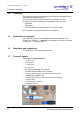
RVC 2-18 CD& HCL 8 Maintenance and service 4 Hexagon socket screw Fig. 43: Removing the hexagon socket screw • 5 6 Pull the thrust piece with the compression spring vertically upwards in order to remove it from the axle. Thrust piece Compression spring Fig. 44: Thrust piece and compression spring • Pull the rotor shaft vertically upwards in order to remove it from the axle. Fig. 45: Removing the rotor shaft Version 04/2012, Rev. 1.
RVC 2-18 CD& HCL 8 Maintenance and service • • Clean the lid with a disinfectant or soap water. Wipe the rotor chamber clean and clean it with soap water or a suitable disinfectant. Cleaning the rotor shaft and magnetic coupling Ensure that no cleaning agent or disinfectant gets into the ball bearings of the rotor shaft as it may wash out the ball bearing grease. This can lead to irreparable damage. CAUTION 7 Rotor shaft with magnetic coupling 8 Lower ball bearing in the rotor shaft Fig.
RVC 2-18 CD& HCL 8 Maintenance and service • 7 Slotted screws 8 Magnetic coupling, separate Separate the magnetic coupling from the rotor shaft. To do so, unscrew the four slotted screws that join the magnetic coupling with the rotor shaft. Fig. 48: Rotor shaft and upper ball bearing • Remove the lower ball bearing. Fig. 49: Removal of the lower ball bearing • • • Clean the rotor shaft and magnetic coupling. Insert a new lower ball bearing. Screw the magnetic coupling and rotor shaft together.
RVC 2-18 CD& HCL 8 Maintenance and service Installation of the rotor shaft • Clean the thrust piece, compression spring, and hexagon socket key. • Clean the cap and grease the O-ring of the cap slightly with vacuum grease. • Insert a new upper ball bearing. • Attach the installation tool (order no. 169181, included in the scope of the supply) to the rotor shaft. 9 Installation tool Fig.
RVC 2-18 CD& HCL 8 Maintenance and service Pos: 165 /20 0 Ch rist/3 71 RVC-BA (PROJEK TE)/RVC 2- 18 CD plus_ 2-1 8 CDplus _HCl/08 0 Wa rtun g un d In stan dhalt ung/ 080 -00 11- 001 0 De ckelschl össe r HCl @ 1 4\m od_ 135 288 799 7560 _68 .docx @ 7 480 7 @ 3 @ 1 8.1.3 Lid locks The locking bolts of both lid locks are exposed to HCl vapours during operation of the RVC and must be protected against corrosion by greasing them with oil for precision engineering at least once a year. • Open the lid.
RVC 2-18 CD& HCL 8 Maintenance and service • • • • Pos: 168 /01 0 Univ ersal mod ule/ Replace any damaged components immediately for your own safety. Immediately rinse off the rotors or accessories if any liquids that may cause corrosion come into contact with them. Clean the accessories outside the rotational vacuum concentrator once a week or preferably after each use.
RVC 2-18 CD& HCL 8 Maintenance and service 8.2 Disinfection of the rotor chamber and accessories • • • • • Use commercially-available disinfectants such as, for example, Incidur®, Meliseptol®, Sagrotan®, Buraton® or Terralin® (available at chemist’s shops or drugstores). The rotational vacuum concentrator and the accessories consist of various materials. A possible incompatibility must be considered.
RVC 2-18 CD& HCL 8 Maintenance and service Pos: 177 /20 0 Ch rist/3 70 RVC-BA (S TANDARDMODULE) /08 0 Wart ung un d Inst and haltu ng/ 080 -004 0 I nsta ndh altun gsar beite n @ 8\m od_1 310 027 462 633 _68. docx @ 47 306 @ 2 @ 1 8.4 Service In the event of service work that requires the removal of the panels, there is a risk of electric shock or mechanical injury. Only qualified specialist personnel is authorised to perform this service work.
RVC 2-18 CD& HCL 8 Maintenance and service Pos: 179 /20 0 Ch rist/3 70 RVC-BA (S TANDARDMODULE) /08 0 Wart ung un d Inst and haltu ng/ 080 -005 0 R ücksen dun g d efekt er Teile @ 8\ mod _13 1002 805 897 6_6 8.do cx @ 4 732 0 @ 2 @ 1 8.5 Return of defective parts Although we exercise great care during the production of our products, it may be necessary to return a unit or accessory to the manufacturer.
RVC 2-18 CD& HCL 9 Disposal Pos: 182 /20 0 Ch rist/3 70 RVC-BA (S TANDARDMODULE) /09 0 Entso rgu ng/0 90 Entso rgu ng= == === == == == === == == === == == === == == === == == == @ 8\ mod _131 002 812 705 5_6 8.doc x @ 4 732 8 @ 1 @ 1 9 Disposal Pos: 183 /20 0 Ch rist/3 70 RVC-BA (S TANDARDMODULE) /09 0 Entso rgu ng/0 90- 001 0 Ent sor gun g des Rota tions -Vakuu m-Ko nzen trat ors @ 8\ mod _13 100 2812 738 3_6 8.do cx @ 4 733 6 @ 2 @ 1 9.
RVC 2-18 CD& HCL 10 Technical data Pos: 188 /20 0 Ch rist/3 71 RVC-BA (PROJEK TE)/RVC 2- 18 CD plus_ 2-1 8 CDplus _HCl/10 0 T ech nische D ate n/10 1 Tech nische Date n HCl= == === == == === == == === == == === == == @ 12 \mo d_1 335 4252 778 50_ 68.
RVC 2-18 CD& HCL 10 Technical data Equipment connections Pos: 189 /01 0 Univ ersal mod ule/ Lee rzeile @ 0\ mo d_12 021 162 445 00_ 0.doc x @ 1 14 @ @ 1 Pos: 190 /01 0 Univ ersal mod ule/ Lee rzeile @ 0\ mo d_12 021 162 445 00_ 0.doc x @ 1 14 @ @ 1 Vacuum connection: Small flange connection DN16KF (ISO 28403, DIN 2861) Aeration valve: Hose nozzle DN3 (outside diameter 4.
RVC 2-18 CD& HCL 11 Appendix Pos: 197 /20 0 Ch rist/3 70 RVC-BA (S TANDARDMODULE) /11 0 Anha ng/ 110 A nha ng= == === == == === == == === == == == === == == === == == === == == == @ 8\ mod_ 131 003 037 974 6_6 8.doc x @ 4 739 1 @ 1 @ 1 11 Appendix Pos: 198 /20 0 Ch rist/3 71 RVC-BA (PROJEK TE)/RVC 2- 18 CD plus_ 2-1 8 CDplus _HCl/11 0 Anh ang/ 110 -00 20 Roto rpr ogr am m @ 9\m od_1 320 657 412 297 _68. docx @ 54 027 @ 2 @ 1 11.
RVC 2-18 CD& HCL 11 Appendix 2.0 10.7 x 72 With round or flat 12 bottom Adapter receiver 25° 1122503) 2.0 11.2 x 36 With flat bottom 36 3 Solid rotor 40° 110188 2.0 16.1 x 56 With flat bottom, micro reaction vessel 18 21) Solid rotor 22° 112351 2.5 11.7 x 32 Chromacol, with flat bottom 24 3 Solid rotor 40° 110517 2.5 12 x 36 With round or flat 24 bottom 3 Solid rotor 40° 110327 4.0 14.8 x 83 With round or flat 12 bottom Adapter receiver 25° 1122493) 4.0 7.0 12.
RVC 2-18 CD& HCL 11 Appendix 10.0 16 x 150 With round bottom 8 1 Disc rotor 32° 112319 10.0 20 x 62 With round or flat 12 bottom, micro reaction vessel 1 Disc rotor 25° 110265 10.0 15.0 alt. 15.0 18.0 30.0 16.5 x 80 – 100 DIN 58970 alternatively 16.5 x 100 – 125 23.8 – 25 x 106 – 120 12 1 alt. 6 With round bottom 8 Disc rotor 25° 124516 1 Disc rotor 18° 110242 30.0 27.5 x 72 With flat bottom 6 1 Disc rotor 22° 1124154) 50.0 28 – 28.
RVC 2-18 CD& HCL 11 Appendix Outside: 50 x 20 -- -- Distance ring 110393 Fixed-angle rotors for RVC 2-18 CDplus HCl All of the products included in this table are acid-resistant and, to a limited extent, also solventresistant. They are made of polypropylene (PP), polyvinylidene fluoride (PVDF), and nickel (Ni). Vessel Rotor Nominal Dimensions volume Description Standard Features Vessels Rotors Configuration per unit Material per rotor Setting angle (reference: vertical) Part no. (ml) 0.25 0.
RVC 2-18 CD& HCL 11 Appendix 2.2 8 x 90 With round or flat bottom 24 1 Solid rotor PVDF 25° 112253 2.5 12 x 36 With flat bottom 24 2 Solid rotor PVDF 40° 112323 4.0 7.0 12.5 x 70 – 100 DIN 58970 18 with round or flat bottom 1 Solid rotor PVDF 25° 112261 5.0 15 x 45 With flat bottom 18 2 Solid rotor PP 40° 110211 5.0 15 x 45 With flat bottom 18 2 Solid rotor PVDF 40° 112298 9.0 13 x 100 13 x 70 – 100 ® Pyrex no.
RVC 2-18 CD& HCL 11 Appendix 50.0 27.3 – 28.7 x 87 – 120 With round bottom 6 1 Disc rotor PVDF, Ni 20° 112332 50.0 29.5 – 30 x 105 – 120 Falcon 6 1 Solid rotor PVDF 20° 1123474) 50.0 29.5 – 30 x 105 – 120 Falcon 6 1 Disc rotor PVDF, Ni 20° 112382 Outside: 50 x 20 -- -- Distance ring PVDF 112361 1) In order to use two rotors,a distance ring, part no. 110393, must be installed between the rotors. Only in conjunction with fixed-angle disc rotor, part no.
RVC 2-18 CD& HCL 11 Appendix Pos: 200 /20 0 Ch rist/3 70 RVC-BA (S TANDARDMODULE) /11 0 Anha ng/ 110 -003 0 Ü bersic ht Abd am pfzeit en @ 8\m od_ 131 0103 584 670 _68 .docx @ 47 421 @ 2 @ 1 11.2 Overview of evaporation times Vessel Water Number of samples Sample volume (ml) Temperature (°C) Pump Cooling trap Total time (min) 10 ml test tube 24 9 45 MZ 2C yes 635 10 ml test tube 24 9 60 MZ 2C yes 510 1.5 ml Eppendorf caps 36 1 30 MZ 2C yes 330 1.
RVC 2-18 CD& HCL 11 Appendix Vessel Number of samples Sample volume (ml) Temperature (°C) Pump Cooling trap Total time (min) Tert. butanol 10 ml test tube 24 9 30 MZ 2C yes 150 C4 H10O 10 ml test tube 24 9 45 MZ 2C yes 105 10 ml test tube 24 9 60 MZ 2C yes 80 1.5 ml Eppendorf caps 36 1 30 MZ 2C yes 55 1.5 ml Eppendorf caps 36 1 45 MZ 2C yes 45 1.
RVC 2-18 CD& HCL 11 Appendix Pos: 202 /20 0 Ch rist/3 71 RVC-BA (PROJEK TE)/RVC 2- 18 CD plus_ 2-1 8 CDplus _HCl/11 0 Anh ang/ 110 -00 41 Kurzb edie nun gsanl eitun g HCl @ 12\m od_ 133 542 656 832 9_68 .docx @ 6 405 8 @ 2 @ 1 11.3 Brief operating instructions 1. Switch the system on via the mains power switch on the right side of the unit. 2. Switch the vacuum pump and/or the cooling trap on. 3. Close the lid. 4.
RVC 2-18 CD& HCL 11 Appendix Functional and operating elements: 1 2 3 4 5 6 Lid lock device Lid Rotor chamber User interface Rotor shaft Mains power switch Fig. 52: Total view of the RVC 2-18 CDplus HCl 7 8 9 Name plate Equipotential bonding screw Connection for mains cable, with a fuse drawer 10 Electrical connection for the stop valve 11 Vacuum connection 12 Connection for aeration Pos: 203 /01 0 Univ ersal mod ule/ 76 Sei tenwe chsel @ 0\ mod _12 021 1624 431 2_0 .docx @ 1 05 @ @ 1 Fig.
RVC 2-18 CD& HCL 11 Appendix Pos: 204 /20 0 Ch rist/3 71 RVC-BA (PROJEK TE)/RVC 2- 18 CD plus_ 2-1 8 CDplus _HCl/11 0 Anh ang/ 110 -00 51 Konfo rmit ätse rklär ung 2-1 8 HCl @ 12\ mod _13 354 2684 809 4_6 8.d ocx @ 6406 6 @ 2 @ 1 11.4 Pos: 205 /01 0 Univ ersal mod ule/ EC-declaration of conformity Sei tenwe chsel @ 0\ mod _12 021 1624 431 2_0 .docx @ 1 05 @ @ 1 Version 04/2012, Rev. 1.
RVC 2-18 CD& HCL 11 Appendix Pos: 206 /01 0 Univ ersal mod ule/9 01 Gl ossa r RVC== == === == == == === == == === == == === == == = @ 8 \mo d_1 309 930 672 666_ 68. docx @ 47 101 @ 1 @ 1 78 Version 04/2012, Rev. 1.
RVC 2-18 CD& HCL 12 Glossary 12 Glossary Boiling retardation The temperature of a liquid can rise above the boiling point without the liquid actually starting to boil. Vibrations or shocks quickly lead to the formation of a large gas bubble that escapes explosively from the vessel. This phenomenon is known as boiling retardation. It occurs when neither the liquid nor the wall of the vessel include any condensation nuclei at which vapour bubbles might form.
RVC 2-18 CD& HCL 12 Glossary Safety pressure Since the vacuum has a dominating influence on the product temperature, Martin Christ Gefriertrocknungsanlagen GmbH has integrated a so-called safety pressure function into their units in order to protect the products. If the pressure inside the rotor chamber rises too quickly – above the safety limit – the energy supply of the unit will be interrupted so that the evaporation process slows down. Fig.
RVC 2-18 CD& HCL Index 13 Index Accessories ......................................... 11, 19 Accessories, cleaning and care.................. 59 Accident prevention ................................... 18 Active phases ............................................ 39 Advantages of the rotational vacuum concentration .......................................... 15 Aeration valve ...................................... 26, 66 Aluminium accessories ..............................
RVC 2-18 CD& HCL Index Equipotential bonding screw .......... 12, 21, 25 Error correction .......................................... 47 Error messages.................................... 21, 47 Evaporation with different tube sizes .......... 34 Evaporation with low capacity .................... 34 Examples of use ........................................ 15 Explanation of symbols .............................. 10 Explanation of the symbols and notes ........ 17 Extended service menu........................
RVC 2-18 CD& HCL Index Operating mode ......................................... 39 Operating personnel .................................. 18 Operating voltage....................................... 25 Options ...................................................... 44 Order number ............................................ 65 Overview of evaporation times ................... 73 P Packaging .................................................. 23 Packaging, disposal ...................................
RVC 2-18 CD& HCL Index Stop valve, electrical connection ................ 12 Stopping the evaporation process prematurely ............................................ 41 Stopping the warm-up phase prematurely.. 40 Storage and transport ................................ 23 Storage conditions ..................................... 23 Stress-corrosion......................................... 59 Supply voltage ........................................... 25 Surface temperature ............................