
Owner's manual


RVC 2-18 CD&
5 Set-up and connection
Version 04/2012, Rev. 1.3 of 25/11/2013 • sb
25
Translation of the original operating manual
Pos: 89 / 200 C hrist /37 0 RV C-B A (STA NDA RD MO DULE )/ 050 Au fstel lu ng u nd Ans chlus s/ 050 -00 30 B elüft u ngsv entil @ 8\m od_ 130941 9388 700 _68 .doc x @ 4 6708 @ 3 @ 1
5.3 Aeration valve
The RVC is equipped with an electromagnetic aeration valve. The rotor
chamber is aerated through this valve after the end of the evaporation
process.
NOTE
Unpressurised inert gas can also be used for aerating the rotor chamber.
Pos: 90 /010 Unive rsalm odule/ L ee rzeile @ 0\ mod _120211 624450 0_0.docx @ 11 4 @ @ 1
Pos: 91 / 200 Chris t /37 0 RVC-B A (S TAND ARD MOD ULE )/050 A u fstell u ng und A ns chluss / 050-00 40 V akuu mve rbi ndung en (au ßer 2- 18 HC L) @ 12\ mod _13 3697 593 9699_6 8.do c x @ 6 4471 @ 3 @ 1
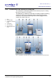
5.4 Vacuum connections
The vacuum connection is realised by way of a vacuum hose with standard
flange connections, clamping rings, or chains, and centring rings.
NOTE
The small flange connections must be installed correctly in order to
prevent leaks (see chapter 7.2.4 - "Small flange connections ").
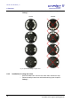
1 Centring ring
2 Clamping ring
3 Flange connection
Fig. 3: Connecting pieces for vacuum connection
Pos: 92 /010 Unive rsalm odule/ Seit enwec hsel @ 0\m od_120 2116244 312_0. docx @ 105 @ @ 1