
Manual


Freeze-dryer EPSILON 2-6 LSCplus
5 Set-up and connection
Version 10/2012, Rev. 1.6 of 16/12/2014 • sb
41
Translation of the original operating manual
Pos: 119 /20 0 Ch rist/3 60 G T-BA L abo r-Pi lot (STAN DAR DMODU LE )/0 50 Aufst ell ung un d Ans chl uss/0 50- 010 0 Gum miventi l e @ 2 5\mod_ 140 498 3741 840 _68.doc x @ 18356 5 @ 2 @ 1
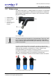
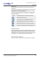
5.11 Rubber valves
The rubber valves (part no. 121860) enable the connection of round-bottom
flasks, wide-neck filter bottles, or distributors for ampoules to a manifold or
drying chamber. Depending on the connector of the components, the blue
plug can be removed.
1 Locking handle
2 Aeration connection
3 Vessel connection
4 Rubber plug
5 Connection to freeze-
dryer (e.g. via a
manifold)
Fig. 22: Rubber valve
NOTE
The rubber valves come supplied in an ungreased state. This is why a thin
layer of vacuum grease must be applied to the connector of the freeze-
dryer as well as to the vessel connector prior to start-up in order to ensure
trouble-free operation.
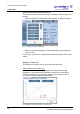
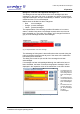
In position A (see figure below), the aeration connector is open and the
vessel connector is closed. The accessory will be aerated while the vacuum
inside the drying chamber is maintained. As a result, vessels can be
exchanged without any interruption of the drying process.
In position B, the aeration connector is closed and the vessel connector is
open. The connected accessory is connected to the freeze-dryer.
In position C, the aeration connector and the vessel connector are closed.
Fig. 23: Possible positions of the locking handle
Pos: 120 /01 0 Uni v ersal mod ule/A bsc hnit tsw echs el @ 0\ mod _12021 245 140 62_ 0.docx @ 418 @ @ 1
Pos: 121 /01 0 Uni v ersal mod ule/S eit enwec hsel @ 0\m od_ 120 211 624 4312 _0. docx @ 10 5 @ @ 1