
Manual


Freeze-dryer EPSILON 2-10D LSCplus
5 Set-up and connection
38
Version 04/2013, Rev. 1.5 of 16/12/2014 • sb
Translation of the original operating manual
Pos: 106 /20 0 Ch rist/3 61 G T-BA L abo r-Pil ot (P ROJE KTE)/E psil on S ta ndard/0 50 Auf s tellun g u nd Ansc hlus s/0 50-005 0 Be dien ung der B elade tür E psil on - Übe rsch rift- -- ------ -- ----- ----- ------ -- ----- ---- @ 25\ mod_140 498 462 812 8_6 8.docx @ 1857 21 @ 2 @ 1
5.5 Operation of the loading door
Pos: 107 /20 0 Ch rist/3 61 G T-BA L abo r-Pi lot (PROJ EK TE)/Epsi lo n Sta nda rd/0 50 Aufs tel lun g und A nsc hluss/ 050- 005 1 Be dien ung der B elade tür E psil on Text @ 2 5\m od_1 404984 629 322 _68. docx @ 18 573 5 @ @ 1
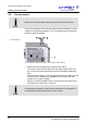
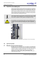
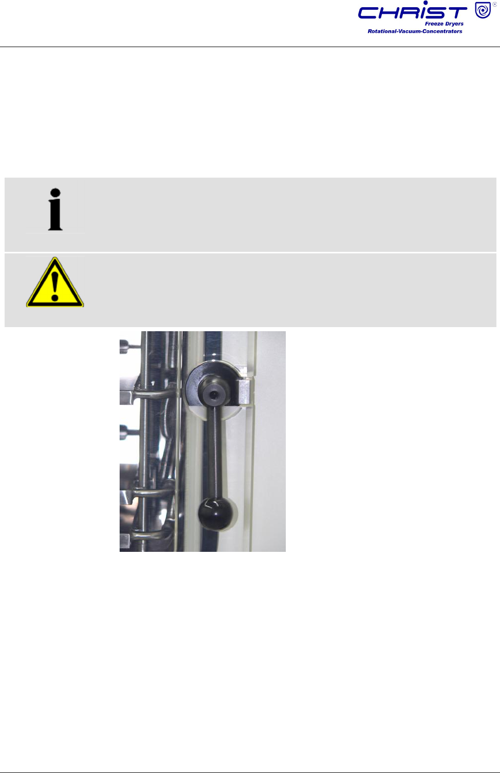
After the drying chamber has been loaded, the loading door is closed and
pressed tightly against the flange of the drying chamber with the aid of the
locking handle. The locking handle is now in a perpendicular position with
regard to the door edge (see figure). When a vacuum builds up inside the
drying chamber during the drying process, the loading door will be pulled
closer to the flange of the drying chamber. As a result, the locking handle
will be loosened and it will hang down loosely.
NOTE
If the locking handle does not hang down perpendicularly when the loading
door is closed, it can be readjusted. To do so, loosen the hexagon socket
screw (size 8), readjust the locking handle, and retighten the screw.
WARNING
Do not tighten the door handle when there is a vacuum inside the drying
chamber. During the aeration, the pressure on the locking handle will
increase to such an extent that the loading door may be damaged beyond
repair!
Fig. 20: Example of a door locking system of the loading door; here: door stop (left side)
Pos: 108 /01 0 Uni v ersal mod ule/L eerz ei le @ 0\m od_ 120 211624 450 0_0. doc x @ 11 4 @ @ 1
Pos: 109 /01 0 Uni v ersal mod ule/L eerz ei le @ 0\m od_ 120 211624 450 0_0. doc x @ 11 4 @ @ 1
Pos: 110 /20 0 Ch rist/3 61 G T-BA Labo r-P ilot (PR OJEK TE)/E psilo n S tanda rd/0 50 A ufs tellun g u nd Ansc hl uss/0 50- 005 2 Hy draul ik Eps ilon -- ----- ----- --- ----- ----- --- ----- -- ------ ----- -- ---- @ 25\ mod_ 140498 463 066 6_6 8.docx @ 1 857 49 @ 2 @ 1
5.6 Hydraulic system
Pos: 111 /20 0 Ch rist/3 61 G T-BA L abor-P ilot (PR OJEK TE)/E psilo n S ta nda rd/050 A ufs tell ung u nd Ans c hluss/0 50- 005 2-0 010 V erfah ren der Stell fläch en Eps il on @ 25\ mod _14049 8463 158 6_6 8.do cx @ 1857 63 @ 3 @ 1
5.7 Manually operated shelf movement
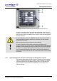
By means of the two push-buttons "Up" (1) and "Down" (2) installed at the
operating panel next to the loading door it is possible to move the shelves
vertically for loading / unloading, stoppering product vials inside the drying
chamber as well as for maintenance purposes. The movement of the
shelves is only possible if the "Up / Down " buttons are pressed
simultaneously (< 0.5 sec) with the push-button "Release" (3) to avoid
injuries ("two-hand control").