
User Manual

Delta 1-24 LSC&
Delta 2-24 LSC&
5 Set-up and connection
34
Version 04/2013, Rev. 1.2 of 20/02/2014 • sb
Translation of the original operating manual
Pos: 98 / 200 Chri st /36 1 GT -BA La bor -Pi lot (P ROJE KTE )/D elt a 1- 24_ 2-24 LS Cpl us /05 0 Aufst el lung un d Ansc hl uss/0 50- 0030 Bel üft ungs ventil D elta @ 15\ mo d_13 553 950 309 15_ 68.d ocx @ 780 60 @ 2 @ 1
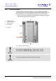
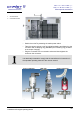
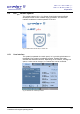
5.3 Aeration valve
The aeration valve is located on top of the left side of the unit (see chapter
2.1.1 - "Functional and operating elements").
After the end of a freeze-drying process, the unit will be aerated via the
aeration valve.
NOTE
The ice condenser chamber can be flooded with nitrogen via the hose
nozzle of the aeration valve.
WARNING
For the aeration with gases under pressure, the client must install a safety
device for pressure relief.
Pos: 99 /010 Unive rsalm odule/ L ee rzeile @ 0\ mod _120211 624450 0_0.docx @ 11 4 @ @ 1
Pos: 100 /01 0 Univ ersal module/ Lee rzeile @ 0\ mo d_12021 162445 00_ 0.docx @ 1 14 @ @ 1
Pos: 101 /20 0 Ch rist/3 61 G T-BA L abo r-Pilot (PR OJEK TE)/Del ta 1 -24 _2-24 LS C plus/0 50 Auf stel lun g und A nsc hluss/ 050 -004 0 Medi ena blaufv entil Del ta @ 15\ mod _13 553 9503139 0_6 8.d ocx @ 7806 8 @ 2 @ 1
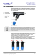
5.4 Media drain valve
The media drain valve is located at the bottom of the left side of the unit
(see chapter 2.1.1 - "Functional and operating elements").
It is used to drain off the condensate and the defrosting water.
• Connect the drain hose (included in the scope of supply) to the hose
connector.
• Place a collecting vessel under the unit.
The hose must be laid with a continuous slope and the end of the hose
must always be above the liquid level in the collecting vessel. This prevents
water and dirt residues from being sucked into the ice condenser chamber
if there is negative pressure when the media drain valve is opened.
Pos: 102 /01 0 Univ ersal module/ Lee rzeile @ 0\ mo d_12021 162445 00_ 0.docx @ 1 14 @ @ 1
Pos: 103 /20 0 C h rist/3 61 G T-BA L abo r-Pil ot (PRO JEK TE)/Del ta 1 -24 _2- 24 LSC plus/0 50 A uf stel lun g u nd Ans c hluss/ 050 -005 0 V ak uum messs ond e Del t a @ 1 5\m od_ 135 539 502 9375 _68 .docx @ 7 8036 @ 2 @ 1
5.5 Vacuum sensor
NOTE
Please refer to the separate operating manual of the vacuum sensor!
In order to protect the vacuum sensor against transport damage, it comes
supplied in its original packaging. Prior to commissioning the freeze-dryer,
the sensor must be installed.